

 DE
USD
DE
USD
-
MenüZurück
-
Marken
-
- Technologien für :
-
Industrie
-
-
- Automatisierung
- Motoren und Antriebe
- Sicherheit
-
Sensoren
- Zubehör/Ersatzteile für Industriesensoren
- Erkennung
- Entfernung
- Scanner
- RFID
-
Prozess
- Durchflusssensor
- Magnetisch-induktiver Durchflussmesser
- Temperaturmessumformer
- Differenzdruckschalter
- Differenzdrucksensor
- Drucktransmitter
- Eintauch-Temperatursensor, passiv
- Füllstandsensor
- Radar-Füllstandsensor
- Vibrationssensor
- Ultraschall-Füllstandmessgerät
- Kapazitiver Füllstandsensor
- Messinstrumente fur Temperatur und Klima
- Temperaturfühler
- Strommessumformer
- Trennverstärker
- Bildverarbeitungssystem (BVS)
- Drehgeber
- Verbindung
- Signal-Kabeln
- Wiegen
- Ventile und Steuerungen
-
Industrie- und Sondersteckvorrichtungen
- CEE-Anbausteckdose (IEC 60309)
- CEE-Kupplung (IEC 60309)
- CEE-Stecker (IEC 60309)
- CEE-Steckdosen-Kombination (IEC 60309)
- CEE-Gerätestecker (IEC 60309)
- CEE-Steckdose (IEC 60309)
- CEE-Steckdose abschaltbar, abgesichert (IEC 60309)
- Explosionsgeschützte CEE-Steckdose (IEC 60309)
- Zubehör/Ersatzteile für CEE-Stecker und -Steckdosen (IEC 60309)
- Zubehor/Ersatzteile fur Test- und Messgerate
- Energieüberwachung
-
-
-
Gebäude
-
-
- Grüne Energie
- HVAC - Klimatisierung
- Beleuchtung
- Überwachen & Vernetzen
- e-Mobilität
-
Automation - Bus Systems
-
Control Elements
- Analogue input for bus system
- Basic module for bus system
- Binary input for bus system
- Central device for bus system
- Controller for home automation systems
- Display for bus system
- I/O device for bus system
- Logic component for bus system
- Signalling and operation panel for bus system
- Light control unit for bus system
- Raumtemperaturregler für Bussystem
- Sensors
- Actuators
- Bus Communications
- Programming
- Others
-
Control Elements
-
Schaltgeräte für Haushalte
- Mehrfachsteckdose
- Abdeckrahmen
- Halterung für Bezeichnungsmaterial
- Steckeradapter
- Steckdose
- Schutzkontaktstecker
- Einsatz/Abdeckung für Kommunikationstechnik
- Installationsschalter
- Bewegungsmelder/Präsenzmelder komplett
- Taster
- Abdeckung/Bedienelement für Installationsschalterprogramme
- USB-Spannungsversorgung
- Bewegungsmelder-Sensor
- Stromverteilungseinheiten (PDU)
- Energieverbrauchsanzeigen
- Emergency call system devices
- Systemgeräte für Klinikinstallation
- Steckbare Gebäudeinstallationssysteme
-
-
-
Elektrifizierung
-
-
-
Installation
- Abzweigdosen
- Befestigungsschellen für Kabel/Rohre
- Installationsrohre aus Metall
-
Isolierung und Verbindung
- Abzweigmuffe (Satz)
- Aderendhülse
- Crimp-Kabelschuh für Aluminiumleiter
- Crimp-Kabelschuh für Kupferleiter
- Formteile wärmeschrumpfend / Breakout-Boot
- Kabelisolationsschlauch
- Klebeband
- Schrumpfschlauch
- Steckklemme
- Steckverbinder für Leuchte
- Verbindung für geschirmte Leitungen
- Zubehör/Ersatzteile für Installations- und Verbindungsmaterial
- Klemme für Leuchte
- Rohrschellen
-
Schutzschlauchsysteme
- Dichtung für Schlauchverschraubung
- Endmuffe für Schutzschlauch
- Geflechtschlauch
- Kabelbündelschlauch
- Kunststoff-Schutzschlauch
- Kunststoff-Wellschlauch
- Metallschutzschlauch
- Verbinder für Kunststoff-Wellschläuche
- Verschraubung für Kunststoff-Schutzschlauch
- Verschraubung für Kunststoff-Wellschlauch
- Verschraubung für Metallschutzschlauch
- Verdrahtungskanäle mit Schlitzen
-
Zubehör für Kabel und Rohre
- Befestigungsklemmen
- Bogen für Installationsrohre
- Dichtklemme für Kabel
- Dichtringe
- Erweiterungs-/Reduzierring
- Gegenmutter für Kabelverschraubung
- Gewindebuchse
- Kabelbinder
- Kabelbinderhalter
- Kabeleinführungstülle
- Kabelverschraubung
- Muffe für Installationsrohre
- Stopfen für Kabelverschraubung
- T-/Kreuzstücke für Installationsrohre
- Zubehör für Unterputz- und Abzweigdosen
- Kabel
- Markierung
-
Niederspannung
- ASC-Verteiler für Baustellen
- Batterien und Batteriemodule
- Baustein für Schutzbeschaltung
-
Befehlsgeräte (Tasten, Wählschalter, Indikatoren )
- Adapter für Befehlsgeräte
- Akustikmelder
- Befehls- und Meldegeräte-Kombination im Gehäuse
- Bezeichnungsschild für Befehlsgeräte
- Fußschalter
- Gehäuse für Befehls- und Meldegeräte
- Knöpfe
- Meldeleuchten / Signalleuchten
- Meldeleuchten / Signalleuchten
- NOT-AUS-Seilzugschalter
- NOT-AUS-Taster, Komplettgerät
- Potentiometer für Befehlsgeräte
- Schutzkappe für Befehlsgeräte
- Signalsäulen
- Steuerschalter, Joystick
- Tastenplatte für Befehls- und Meldegeräte
- Wahlschalter
- Zubehör/Ersatzteile für Befehlsgeräte
- Zubehör/Ersatzteile für NOT-AUS-Seilzugschalter
- Zweihandpult
- DIN-Schienenadapter
- Filter für Niederspannung
- Gleichstromversorgung
- Kontaktoren
- Lasttrennschalter
- Leistungskondensatoren
-
Motorstart & Schutz
- Bedienbaustein für Motormanagement-Gerät
- Erweiterungsmodul für Motormanagement-Gerät
- Leistungsschalter für Motorschutz
- Motormanagement-Gerät
- Motorstarter/Motorstarterkombination
- Sanftstarter
- Überlastrelais elektronisch
- Überlastrelais thermisch
- Zubehör/Ersatzteile für elektronisches Motorsteuer- und Schutzgerät
-
Schränke & Gehäuse
- Befestigungsschelle für Kabel/Rohre
- Clé de boîtier / d'armoire
- Clima Control
- Elektronik-Leergehäuse
-
Energieverteilungssysteme
- Abdeckkappe für Hauptleitungsklemme
- Abdeckungen für Verteiler
- Abgangskasten für Schienenverteiler
- Befestigungssystem für Schienenverteiler
- DIN-Schiene
- Einspeisekasten für Schienenverteiler
- Hauptleitungsklemme
- Installationskleinverteiler
- Montageplatte für Verteilergehäuse
- Phasen-Trennplatte
- Sammelschienenträger
- Sammelschienenverbinder
- Schienenverteilereinheit
- Verteilerbaugruppe Klemmen
- Verteilerbaugruppe Leitungsschutzschalter
- Verteilerfeld für Installationsverteiler
- Zähler-Komplettschrank
- Zubehör/Ersatzteile für Sammelschienen
- Zubehör/Ersatzteile für Schienenverteiler
- Gehäuse/Schrank für Explosionsschutz
- Leergehäuse
- Montagezubehör (Schaltschrank)
- Network/server enclosure
- Netzwerkgehäuse
- Schließsystem für Schaltschranksysteme
- Sockel/Sockelelement (Schaltschrank)
- Tür/Bedientableau (Schaltschrank)
-
Stromkreisunterbrecher
- Ausgelöstmelder
- Fehlerstrom-Schutzschalter
- Geräteschutzschalter
- Hilfsschalterblock
- Kombination FI-Schalter/Leitungsschutzschalter
- Lastschalter
-
Leistungsschalter für Trafo-, Generator- und Anlagenschutz
- Arbeitsstromauslöser
- Auslöseblock für Leistungsschalter
- Elektrischer Antrieb für Leistungsschalter
- Handantrieb für Schaltgeräte
- Handgriff für Schaltgeräte
- Phasentrenner für Leistungsschalter
- Schaltspule für Leistungsschalter
- Sockel für Leistungsschalter
- Umbausatz für Leistungsschalter
- Unterspannungsauslöser
- Verdrahtungsset für Leistungsschalter
- Leitungsschutzschalter
- Sammelschienen-Adapter
- Selektiver Hauptleitungsschutzschalter
- Sicherungen
- Sicherungslasttrennschalter
- Überspannungsableiter für Energietechnik/Stromversorgung
-
Thermospannungs-Reihenklemme
- Abschluss- und Zwischenplatte für Reihenklemme
- Bauelement-Reihenklemme
- Bauelementestecker
- Durchgangs-Reihenklemme
- Ein- und mehrpolige Klemmenleiste
- Endklammer/-halter für Reihenklemme
- Initiator/Aktor-Reihenklemme
- Installations-Etagenklemme
- Klemmenmarkierung
- Querverbinder/Brücker für Reihenklemme
- Reihenklemmen-Steckadapter
- Schirmanschlussklemme
- Schutzleiter-Reihenklemme
- Sicherungs-Reihenklemme
- Testadapter für Reihenklemmen
- Trenn- und Messtrenn-Reihenklemme
- Zubehör/Ersatzteile für Klemmen
- Transformatoren und Spulen
- Überspannungsschutz für Daten-/Signalleitungen
- Zubehör/Ersatzteile für Niederspannungs-Schalttechnik
-
Zweihandschaltgerät
- Differenzstrom-Überwachungsgerät
- Drehzahl-/Stillstandüberwachungsgerät
- Füllstand-/Niveauüberwachungsgerät
- Halbleiterrelais
- Installationsrelais
- Isolations-/Erdschlussüberwachungsgerät
- Optokoppler
- Phasenüberwachungsgerät
- Relaissockel
- Schaltrelais
- Spannungsüberwachungsgerät
- Stromüberwachungsgerät
- Télérupteur
- Temperaturüberwachungsgerät
- Thermistormotorschutzrelais
- Zeitblöcke
- Zeitrelais
- Zubehör/Ersatzteile für Schaltrelais
- Optische und akustische Signalgeräte
- UPS
-
Installation
-
-
-
Werkzeuge
-
- Kontaktieren Sie uns
- Über Uns
- Promo
-
PLC-City
Via Circumvallazione esterna 12
80025 Casandrino NA
Italien
-
MenüZurück
-
Marken
-
- Technologien für :
-
Industrie
-
-
- Automatisierung
- Motoren und Antriebe
- Sicherheit
-
Sensoren
- Zubehör/Ersatzteile für Industriesensoren
- Erkennung
- Entfernung
- Scanner
- RFID
-
Prozess
- Durchflusssensor
- Magnetisch-induktiver Durchflussmesser
- Temperaturmessumformer
- Differenzdruckschalter
- Differenzdrucksensor
- Drucktransmitter
- Eintauch-Temperatursensor, passiv
- Füllstandsensor
- Radar-Füllstandsensor
- Vibrationssensor
- Ultraschall-Füllstandmessgerät
- Kapazitiver Füllstandsensor
- Messinstrumente fur Temperatur und Klima
- Temperaturfühler
- Strommessumformer
- Trennverstärker
- Bildverarbeitungssystem (BVS)
- Drehgeber
- Verbindung
- Signal-Kabeln
- Wiegen
- Ventile und Steuerungen
-
Industrie- und Sondersteckvorrichtungen
- CEE-Anbausteckdose (IEC 60309)
- CEE-Kupplung (IEC 60309)
- CEE-Stecker (IEC 60309)
- CEE-Steckdosen-Kombination (IEC 60309)
- CEE-Gerätestecker (IEC 60309)
- CEE-Steckdose (IEC 60309)
- CEE-Steckdose abschaltbar, abgesichert (IEC 60309)
- Explosionsgeschützte CEE-Steckdose (IEC 60309)
- Zubehör/Ersatzteile für CEE-Stecker und -Steckdosen (IEC 60309)
- Zubehor/Ersatzteile fur Test- und Messgerate
- Energieüberwachung
-
-
-
Gebäude
-
-
- Grüne Energie
- HVAC - Klimatisierung
- Beleuchtung
- Überwachen & Vernetzen
- e-Mobilität
-
Automation - Bus Systems
-
Control Elements
- Analogue input for bus system
- Basic module for bus system
- Binary input for bus system
- Central device for bus system
- Controller for home automation systems
- Display for bus system
- I/O device for bus system
- Logic component for bus system
- Signalling and operation panel for bus system
- Light control unit for bus system
- Raumtemperaturregler für Bussystem
- Sensors
- Actuators
- Bus Communications
- Programming
- Others
-
Control Elements
-
Schaltgeräte für Haushalte
- Mehrfachsteckdose
- Abdeckrahmen
- Halterung für Bezeichnungsmaterial
- Steckeradapter
- Steckdose
- Schutzkontaktstecker
- Einsatz/Abdeckung für Kommunikationstechnik
- Installationsschalter
- Bewegungsmelder/Präsenzmelder komplett
- Taster
- Abdeckung/Bedienelement für Installationsschalterprogramme
- USB-Spannungsversorgung
- Bewegungsmelder-Sensor
- Stromverteilungseinheiten (PDU)
- Energieverbrauchsanzeigen
- Emergency call system devices
- Systemgeräte für Klinikinstallation
- Steckbare Gebäudeinstallationssysteme
-
-
-
Elektrifizierung
-
-
-
Installation
- Abzweigdosen
- Befestigungsschellen für Kabel/Rohre
- Installationsrohre aus Metall
-
Isolierung und Verbindung
- Abzweigmuffe (Satz)
- Aderendhülse
- Crimp-Kabelschuh für Aluminiumleiter
- Crimp-Kabelschuh für Kupferleiter
- Formteile wärmeschrumpfend / Breakout-Boot
- Kabelisolationsschlauch
- Klebeband
- Schrumpfschlauch
- Steckklemme
- Steckverbinder für Leuchte
- Verbindung für geschirmte Leitungen
- Zubehör/Ersatzteile für Installations- und Verbindungsmaterial
- Klemme für Leuchte
- Rohrschellen
-
Schutzschlauchsysteme
- Dichtung für Schlauchverschraubung
- Endmuffe für Schutzschlauch
- Geflechtschlauch
- Kabelbündelschlauch
- Kunststoff-Schutzschlauch
- Kunststoff-Wellschlauch
- Metallschutzschlauch
- Verbinder für Kunststoff-Wellschläuche
- Verschraubung für Kunststoff-Schutzschlauch
- Verschraubung für Kunststoff-Wellschlauch
- Verschraubung für Metallschutzschlauch
- Verdrahtungskanäle mit Schlitzen
-
Zubehör für Kabel und Rohre
- Befestigungsklemmen
- Bogen für Installationsrohre
- Dichtklemme für Kabel
- Dichtringe
- Erweiterungs-/Reduzierring
- Gegenmutter für Kabelverschraubung
- Gewindebuchse
- Kabelbinder
- Kabelbinderhalter
- Kabeleinführungstülle
- Kabelverschraubung
- Muffe für Installationsrohre
- Stopfen für Kabelverschraubung
- T-/Kreuzstücke für Installationsrohre
- Zubehör für Unterputz- und Abzweigdosen
- Kabel
- Markierung
-
Niederspannung
- ASC-Verteiler für Baustellen
- Batterien und Batteriemodule
- Baustein für Schutzbeschaltung
-
Befehlsgeräte (Tasten, Wählschalter, Indikatoren )
- Adapter für Befehlsgeräte
- Akustikmelder
- Befehls- und Meldegeräte-Kombination im Gehäuse
- Bezeichnungsschild für Befehlsgeräte
- Fußschalter
- Gehäuse für Befehls- und Meldegeräte
- Knöpfe
- Meldeleuchten / Signalleuchten
- Meldeleuchten / Signalleuchten
- NOT-AUS-Seilzugschalter
- NOT-AUS-Taster, Komplettgerät
- Potentiometer für Befehlsgeräte
- Schutzkappe für Befehlsgeräte
- Signalsäulen
- Steuerschalter, Joystick
- Tastenplatte für Befehls- und Meldegeräte
- Wahlschalter
- Zubehör/Ersatzteile für Befehlsgeräte
- Zubehör/Ersatzteile für NOT-AUS-Seilzugschalter
- Zweihandpult
- DIN-Schienenadapter
- Filter für Niederspannung
- Gleichstromversorgung
- Kontaktoren
- Lasttrennschalter
- Leistungskondensatoren
-
Motorstart & Schutz
- Bedienbaustein für Motormanagement-Gerät
- Erweiterungsmodul für Motormanagement-Gerät
- Leistungsschalter für Motorschutz
- Motormanagement-Gerät
- Motorstarter/Motorstarterkombination
- Sanftstarter
- Überlastrelais elektronisch
- Überlastrelais thermisch
- Zubehör/Ersatzteile für elektronisches Motorsteuer- und Schutzgerät
-
Schränke & Gehäuse
- Befestigungsschelle für Kabel/Rohre
- Clé de boîtier / d'armoire
- Clima Control
- Elektronik-Leergehäuse
-
Energieverteilungssysteme
- Abdeckkappe für Hauptleitungsklemme
- Abdeckungen für Verteiler
- Abgangskasten für Schienenverteiler
- Befestigungssystem für Schienenverteiler
- DIN-Schiene
- Einspeisekasten für Schienenverteiler
- Hauptleitungsklemme
- Installationskleinverteiler
- Montageplatte für Verteilergehäuse
- Phasen-Trennplatte
- Sammelschienenträger
- Sammelschienenverbinder
- Schienenverteilereinheit
- Verteilerbaugruppe Klemmen
- Verteilerbaugruppe Leitungsschutzschalter
- Verteilerfeld für Installationsverteiler
- Zähler-Komplettschrank
- Zubehör/Ersatzteile für Sammelschienen
- Zubehör/Ersatzteile für Schienenverteiler
- Gehäuse/Schrank für Explosionsschutz
- Leergehäuse
- Montagezubehör (Schaltschrank)
- Network/server enclosure
- Netzwerkgehäuse
- Schließsystem für Schaltschranksysteme
- Sockel/Sockelelement (Schaltschrank)
- Tür/Bedientableau (Schaltschrank)
-
Stromkreisunterbrecher
- Ausgelöstmelder
- Fehlerstrom-Schutzschalter
- Geräteschutzschalter
- Hilfsschalterblock
- Kombination FI-Schalter/Leitungsschutzschalter
- Lastschalter
-
Leistungsschalter für Trafo-, Generator- und Anlagenschutz
- Arbeitsstromauslöser
- Auslöseblock für Leistungsschalter
- Elektrischer Antrieb für Leistungsschalter
- Handantrieb für Schaltgeräte
- Handgriff für Schaltgeräte
- Phasentrenner für Leistungsschalter
- Schaltspule für Leistungsschalter
- Sockel für Leistungsschalter
- Umbausatz für Leistungsschalter
- Unterspannungsauslöser
- Verdrahtungsset für Leistungsschalter
- Leitungsschutzschalter
- Sammelschienen-Adapter
- Selektiver Hauptleitungsschutzschalter
- Sicherungen
- Sicherungslasttrennschalter
- Überspannungsableiter für Energietechnik/Stromversorgung
-
Thermospannungs-Reihenklemme
- Abschluss- und Zwischenplatte für Reihenklemme
- Bauelement-Reihenklemme
- Bauelementestecker
- Durchgangs-Reihenklemme
- Ein- und mehrpolige Klemmenleiste
- Endklammer/-halter für Reihenklemme
- Initiator/Aktor-Reihenklemme
- Installations-Etagenklemme
- Klemmenmarkierung
- Querverbinder/Brücker für Reihenklemme
- Reihenklemmen-Steckadapter
- Schirmanschlussklemme
- Schutzleiter-Reihenklemme
- Sicherungs-Reihenklemme
- Testadapter für Reihenklemmen
- Trenn- und Messtrenn-Reihenklemme
- Zubehör/Ersatzteile für Klemmen
- Transformatoren und Spulen
- Überspannungsschutz für Daten-/Signalleitungen
- Zubehör/Ersatzteile für Niederspannungs-Schalttechnik
-
Zweihandschaltgerät
- Differenzstrom-Überwachungsgerät
- Drehzahl-/Stillstandüberwachungsgerät
- Füllstand-/Niveauüberwachungsgerät
- Halbleiterrelais
- Installationsrelais
- Isolations-/Erdschlussüberwachungsgerät
- Optokoppler
- Phasenüberwachungsgerät
- Relaissockel
- Schaltrelais
- Spannungsüberwachungsgerät
- Stromüberwachungsgerät
- Télérupteur
- Temperaturüberwachungsgerät
- Thermistormotorschutzrelais
- Zeitblöcke
- Zeitrelais
- Zubehör/Ersatzteile für Schaltrelais
- Optische und akustische Signalgeräte
- UPS
-
Installation
-
-
-
Werkzeuge
-
- Kontaktieren Sie uns
- Über Uns
- Promo
VAA-4E4A-KE5-ZEJQ/R PEPPERL+FUCHS - Part number: 269780
PEPPERL+FUCHS
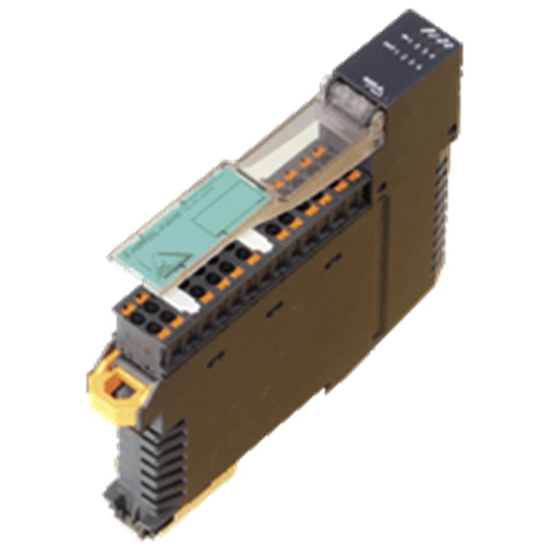
AS-Interface sensor/actuator module VAA-4E4A-KE5-ZEJQ/R VAA-4E4A-KE5-ZEJQ/R Housing with push-in connection technology and mechanically coded terminal blocks Housing width 19 mm, installation in the switch cabinet on DIN mounting rail Selectable supply to the sensors: External or from the module Function display for bus, internal sensor supply, inputs, and outputs AS-Interface sensor/actuator module VAA-4E4A-KE5-ZEJQ/R VAA-4E4A-KE5-ZEJQ/R Housing with push-in connection technology and mechanically coded terminal blocks Housing width 19 mm, installation in the switch cabinet on DIN mounting rail Selectable supply to the sensors: External or from the module Function display for bus, internal sensor supply, inputs, and outputs
Das Produktbild dient nur zur Veranschaulichung.
Das Ursprungsland, der HS-Code und die Beschreibung werden vom Hersteller angegeben und können ohne vorherige Ankündigung geändert werden. Aus diesem Grund kann PLC-City nicht für Abweichungen verantwortlich gemacht werden.


 und viele weitere
Wir akzeptieren viele Zahlungsmethoden: Banküberweisung (SEPA, ACH), Debit/ Kreditkarten (Mastercard, VISA, American Express, Diners Club, Discover, JCB, UnionPay), PayPal, ApplePay, GooglePay, Link by Stripe, Cartes Bancaires, Alipay, Bancontact, blik, eps, giropay Deal, Przelewy24, WeChatPay.
Weitere Informationen zu unseren Zahlungsmethoden
Dieses Produkt ist durch eine 12 Monaten Garantie abgedeckt, gültig für Herstellungsfehler oder Fehlfunktionen. Die Garantie deckt keine Schäden ab, die durch unsachgemäßen Gebrauch oder versehentliche Beschädigung verursacht wurden.
Erfahren Sie mehr über unsere Garantie
Rückgaben bedürfen einer vorherigen Genehmigung und werden als Store-Gutschrift erstattet. Vorbestellte Artikel sind ausgeschlossen.

 und viele weitere
Wir akzeptieren viele Zahlungsmethoden: Banküberweisung (SEPA, ACH), Debit/ Kreditkarten (Mastercard, VISA, American Express, Diners Club, Discover, JCB, UnionPay), PayPal, ApplePay, GooglePay, Link by Stripe, Cartes Bancaires, Alipay, Bancontact, blik, eps, giropay Deal, Przelewy24, WeChatPay.
Weitere Informationen zu unseren Zahlungsmethoden
Dieses Produkt ist durch eine 12 Monaten Garantie abgedeckt, gültig für Herstellungsfehler oder Fehlfunktionen. Die Garantie deckt keine Schäden ab, die durch unsachgemäßen Gebrauch oder versehentliche Beschädigung verursacht wurden.
Erfahren Sie mehr über unsere Garantie
Rückgaben bedürfen einer vorherigen Genehmigung und werden als Store-Gutschrift erstattet. Vorbestellte Artikel sind ausgeschlossen.