VAA-4E4A-KE5-ZEJQ/R PEPPERL+FUCHS - Part number: 269780
غير متوفر - طلب متأخر
لطلب من الشركة المصنعة
310.69 USD

ضرائب الاستيراد غير مشمولة

عليك التسجيل

VAA-4E4A-KE5-ZEJQ/R PEPPERL+FUCHS - Part number: 269780

PEPPERL+FUCHS
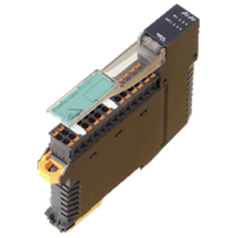
AS-Interface sensor/actuator module VAA-4E4A-KE5-ZEJQ/R VAA-4E4A-KE5-ZEJQ/R Housing with push-in connection technology and mechanically coded terminal blocks Housing width 19 mm, installation in the switch cabinet on DIN mounting rail Selectable supply to the sensors: External or from the module Function display for bus, internal sensor supply, inputs, and outputs AS-Interface sensor/actuator module VAA-4E4A-KE5-ZEJQ/R VAA-4E4A-KE5-ZEJQ/R Housing with push-in connection technology and mechanically coded terminal blocks Housing width 19 mm, installation in the switch cabinet on DIN mounting rail Selectable supply to the sensors: External or from the module Function display for bus, internal sensor supply, inputs, and outputs

شبكات MPN 269780, PEP269780, VAA-4E4A-KE5-ZEJQ/R
رمز النظام المنسق 85371091
Weight 0.13 kg

صورة المنتج هي لأغراض توضيحية فقط.
يتم توفير بلد المنشأ ورمز النظام المنسق والوصف من قبل الشركة المصنعة وقد تكون عرضة للتغيير دون إشعار مسبق. ولهذا السبب، لا يمكن تحميل شركة PLC-City المسؤولية عن أي اختلافات.
تم بيعه بواسطة PLC-CITY® وتم شحنه من إيطاليا

نحن نقبل العديد من طرق الدفع: التحويل البنكي (SEPA، ACH)، بطاقات الخصم/الائتمان (Mastercard، VISA، American Express، Diners Club، Discover، JCB، UnionPay)، PayPal، ApplePay، GooglePay، link by Stripe، Cartes Bancaires، Alipay، Bancontact، blik، eps، giropay iDeal، Przelewy24، WeChatPay.
مزيد من المعلومات حول طرق الدفع لدينا

هذا المنتج مشمول بضمان 12 شهور، صالح لعيوب التصنيع أو الأعطال. لا يغطي الضمان الأضرار الناجمة عن الاستخدام غير السليم أو الأضرار العرضية.
تعرف على المزيد حول الضمان الخاص بنا

يُشترط الحصول على موافقة مسبقة لإجراء الإرجاع، ويتم إصدار رصيد بدلاً من استرداد نقدي. الطلبات المسبقة (Backorder) غير مشمولة.

اطلع على سياسة الإرجاع الخاصة بنا

310.69 USD

ضرائب الاستيراد غير مشمولة

عليك التسجيل
تم بيعه بواسطة PLC-CITY® وتم شحنه من إيطاليا
نحن شريك متخصص لـ PEPPERL+FUCHS
شحن سريع مجاني إلى الولايات المتحدة الأمريكية
Loader...
عرض جميع خدمات الشحن
اطلب عرض أسعار لمعرفة تاريخ التسليم

نحن نقبل العديد من طرق الدفع: التحويل البنكي (SEPA، ACH)، بطاقات الخصم/الائتمان (Mastercard، VISA، American Express، Diners Club، Discover، JCB، UnionPay)، PayPal، ApplePay، GooglePay، link by Stripe، Cartes Bancaires، Alipay، Bancontact، blik، eps، giropay iDeal، Przelewy24، WeChatPay.
مزيد من المعلومات حول طرق الدفع لدينا

هذا المنتج مشمول بضمان 12 شهور، صالح لعيوب التصنيع أو الأعطال. لا يغطي الضمان الأضرار الناجمة عن الاستخدام غير السليم أو الأضرار العرضية.
تعرف على المزيد حول الضمان الخاص بنا

يُشترط الحصول على موافقة مسبقة لإجراء الإرجاع، ويتم إصدار رصيد بدلاً من استرداد نقدي. الطلبات المسبقة (Backorder) غير مشمولة.

اطلع على سياسة الإرجاع الخاصة بنا

احصل على عرض الأسعار الشخصي الخاص بك الآن

سيساعدك مندوب المبيعات المخصص على تقديم أفضل الأسعار وأوقات التسليم.

عليك التسجيل

معلومات المنتج

وصف

Datasheet excerpt: Technical data of  VAA-4E4A-KE5-ZEJQ/R Product Description Cabinet module4 inputs and 4 relay outputs General specifications Node typeStandard node AS-Interface specificationV3.0 Required master specification≥ V2.0 UL File NumberE223772 MTBF224 a Indicators/operating means LED FAULTFault display; Red LEDred: Communication fault or address is 0red, flashing: Overload, internal input supply LED INTInternal input supply active; LED green LED PWRAS-Interface voltage; green LEDgreen: voltage OKflashing green: address 0 LED INswitching state (input); 4 LED yellow LED OUTSwitching state (output); 4 LED yellow Electrical specifications Auxiliary voltage (input)12 ... 30 V DC PELV Rated operating voltage26.5 ... 31.6 V from AS-Interface Rated operating current≤ 35 mA (without sensors) / max. 230 mA Surge protectionO1 ... O4: Over voltage category IIUEXT, Ue: overvoltage category II, safe isolated power supplies (PELV) Input Number/Type4 inputs for 3-wire sensors (PNP), DC Supplyfrom AS-Interface (switch position INT, default settings) or external UEXT (switch position EXT) Voltage21 ... 31 V DC (INT) Current loading capacity≤ 150 mA, overload- and short-circuit protected (INT) Input current≤ 5.6 mA (max.) Switching pointaccording to DIN EN 61131-2 (type 1) 0 (unattenuated)≤ 0.5 mA 1 (attenuated)≥ 2 mA Signal delay< 1 ms (input/AS-Interface) Output Number/Type4 relay outputs, normally open Supplynone Nominal load Per contact2 A/30 VDC; 2 A/250 VAC For more information, see the "Galvanic Isolation" section Per module8 A Control circuit≤ 11 mA per relay (from AS-Interface) Switching delay< 10 ms (AS-Interface/contact) Usage categoryDC-13 and AC-14 Switching Mechanical5 x 107 Electrical2 x 105 (250 VAC, 2 A, cos φ = 0.4) Galvanic isolation Input/Outputsafe isolation, Rated insulation voltage 252 Veff Input/AS-InterfaceSwitch position INT: None Switch setting EXT: safe isolation, rated insulation voltage 92 Veff Output/OutputBasic insulation, rated insulation voltage 250 Veff, in phase Output/AS-Interfacesafe isolation, Rated insulation voltage 252 Veff Directive conformity Electromagnetic compatibility Directive 2014/30/EUEN 62026-2:2013 EN 61000-6-2:2005, EN 61000-6-4:2007 Low voltage Directive 2006/95/ECEN 60664-1:2007 Standard conformity Galvanic isolationEN 60664-1:2007 Degree of protectionEN 60529:2000 Fieldbus standardEN 62026-2:2013 Electrical safetyIEC 61140:2009 InputEN 61131-2:2004 Emitted interferenceEN 61000-6-4:2007 AS-InterfaceEN 62026-2:2013 Noise immunityEN 61000-6-2:2005, EN 61326-1:2006, EN 62026:2013 Programming instructions ProfileS-7.0 IO code7 ID code0 ID1 codeF ID2 codeE Data bits (function via AS-Interface) input output D0 IN1 O1 D1 IN2 O2 D2 IN3 O3 D3 IN4 O4 Parameter bits (programmable via AS-i)function P0Communication monitoringP0 = 0 monitoring = off, the outputs maintain the status if communication failsP0 = 1 monitoring = on, i.e. if communication fails, the outputs are deenergised (default settings) P1Input filterP1 = 0 input filter on, pulse suppression ≤ 2 msP1 = 1 input filter off (default settings) P2Synchronous modeP2 = 0 synchronous mode onP2 = 1 synchronous mode off (default settings) P3not used Ambient conditions Ambient temperature-25 ... 60 °C (-13 ... 140 °F) Storage temperature-25 ... 85 °C (-13 ... 185 °F) Relative humidity85 % , noncondensing Climatic conditionsFor indoor use only Altitude≤ 2000 m above MSL Shock and impact resistance15 g, 11 ms in 6 spatial directions, 3 shocks 10 g, 16 ms in 6 spatial directions, 1000 shocks Vibration resistance0.35 mm 10 ... 57 Hz , 5 g 57 ... 150 Hz, 20 cycles Pollution degree2 Mechanical specifications Degree of protectionIP20 Installation in an enclosure with a minimum protection class of IP54 required ConnectionRemovable push-in terminalsrated connection capacity:rigid: 0.20 mm2 ... 1.5 mm2flexible (without wire end ferrule): 0.20 mm2 ... 2.5 mm2flexible (with wire end ferrule): 0.25 mm2 ... 1.5 mm2 Material HousingPA 66-FR Mass125 g MountingDIN mounting rail Classifications SystemClasscode ECLASS 11.027242604 ECLASS 10.0.127242604 ECLASS 9.027242604 ECLASS 8.027242604 ECLASS 5.127242604 ETIM 8.0EC001599 ETIM 7.0EC001599 ETIM 6.0EC001599 ETIM 5.0EC001599 UNSPSC 12.139121535 Datasheet excerpt: Technical data of  VAA-4E4A-KE5-ZEJQ/R Product Description Cabinet module4 inputs and 4 relay outputs General specifications Node typeStandard node AS-Interface specificationV3.0 Required master specification≥ V2.0 UL File NumberE223772 MTBF224 a Indicators/operating means LED FAULTFault display; Red LEDred: Communication fault or address is 0red, flashing: Overload, internal input supply LED INTInternal input supply active; LED green LED PWRAS-Interface voltage; green LEDgreen: voltage OKflashing green: address 0 LED INswitching state (input); 4 LED yellow LED OUTSwitching state (output); 4 LED yellow Electrical specifications Auxiliary voltage (input)12 ... 30 V DC PELV Rated operating voltage26.5 ... 31.6 V from AS-Interface Rated operating current≤ 35 mA (without sensors) / max. 230 mA Surge protectionO1 ... O4: Over voltage category IIUEXT, Ue: overvoltage category II, safe isolated power supplies (PELV) Input Number/Type4 inputs for 3-wire sensors (PNP), DC Supplyfrom AS-Interface (switch position INT, default settings) or external UEXT (switch position EXT) Voltage21 ... 31 V DC (INT) Current loading capacity≤ 150 mA, overload- and short-circuit protected (INT) Input current≤ 5.6 mA (max.) Switching pointaccording to DIN EN 61131-2 (type 1) 0 (unattenuated)≤ 0.5 mA 1 (attenuated)≥ 2 mA Signal delay< 1 ms (input/AS-Interface) Output Number/Type4 relay outputs, normally open Supplynone Nominal load Per contact2 A/30 VDC; 2 A/250 VAC For more information, see the "Galvanic Isolation" section Per module8 A Control circuit≤ 11 mA per relay (from AS-Interface) Switching delay< 10 ms (AS-Interface/contact) Usage categoryDC-13 and AC-14 Switching Mechanical5 x 107 Electrical2 x 105 (250 VAC, 2 A, cos φ = 0.4) Galvanic isolation Input/Outputsafe isolation, Rated insulation voltage 252 Veff Input/AS-InterfaceSwitch position INT: None Switch setting EXT: safe isolation, rated insulation voltage 92 Veff Output/OutputBasic insulation, rated insulation voltage 250 Veff, in phase Output/AS-Interfacesafe isolation, Rated insulation voltage 252 Veff Directive conformity Electromagnetic compatibility Directive 2014/30/EUEN 62026-2:2013 EN 61000-6-2:2005, EN 61000-6-4:2007 Low voltage Directive 2006/95/ECEN 60664-1:2007 Standard conformity Galvanic isolationEN 60664-1:2007 Degree of protectionEN 60529:2000 Fieldbus standardEN 62026-2:2013 Electrical safetyIEC 61140:2009 InputEN 61131-2:2004 Emitted interferenceEN 61000-6-4:2007 AS-InterfaceEN 62026-2:2013 Noise immunityEN 61000-6-2:2005, EN 61326-1:2006, EN 62026:2013 Programming instructions ProfileS-7.0 IO code7 ID code0 ID1 codeF ID2 codeE Data bits (function via AS-Interface) input output D0 IN1 O1 D1 IN2 O2 D2 IN3 O3 D3 IN4 O4 Parameter bits (programmable via AS-i)function P0Communication monitoringP0 = 0 monitoring = off, the outputs maintain the status if communication failsP0 = 1 monitoring = on, i.e. if communication fails, the outputs are deenergised (default settings) P1Input filterP1 = 0 input filter on, pulse suppression ≤ 2 msP1 = 1 input filter off (default settings) P2Synchronous modeP2 = 0 synchronous mode onP2 = 1 synchronous mode off (default settings) P3not used Ambient conditions Ambient temperature-25 ... 60 °C (-13 ... 140 °F) Storage temperature-25 ... 85 °C (-13 ... 185 °F) Relative humidity85 % , noncondensing Climatic conditionsFor indoor use only Altitude≤ 2000 m above MSL Shock and impact resistance15 g, 11 ms in 6 spatial directions, 3 shocks 10 g, 16 ms in 6 spatial directions, 1000 shocks Vibration resistance0.35 mm 10 ... 57 Hz , 5 g 57 ... 150 Hz, 20 cycles Pollution degree2 Mechanical specifications Degree of protectionIP20 Installation in an enclosure with a minimum protection class of IP54 required ConnectionRemovable push-in terminalsrated connection capacity:rigid: 0.20 mm2 ... 1.5 mm2flexible (without wire end ferrule): 0.20 mm2 ... 2.5 mm2flexible (with wire end ferrule): 0.25 mm2 ... 1.5 mm2 Material HousingPA 66-FR Mass125 g MountingDIN mounting rail Classifications SystemClasscode ECLASS 11.027242604 ECLASS 10.0.127242604 ECLASS 9.027242604 ECLASS 8.027242604 ECLASS 5.127242604 ETIM 8.0EC001599 ETIM 7.0EC001599 ETIM 6.0EC001599 ETIM 5.0EC001599 UNSPSC 12.139121535

مراجعات شركتنا