

 ES
USD
ES
USD
-
MenúRegreso
-
Marcas
-
- Tecnologías para :
-
Industria
-
-
Edificios
-
-
Electrificación
-
-
-
Baja tensión
- Accesorios para la tecnología de conmutación de baja tensión
- Adaptadores para carril DIN
-
Armarios & Carcasas
- Abrazaderas de montaje
- Accesorios de montaje (armarios de distribución)
- Armarios vacíos
- Bases/elementos base
- Carcasas de red
- Carcasas para electrónica
- Carcasas/armarios para protección contra explosiones
- Clima Control
- Llaves de cajón/armario
- Network/server enclosure
- Puertas/paneles de control
- Sistemas de bloqueo para sistemas de armarios de control
-
Sistemas de distribución de energía
- Accesorios para barras colectoras
- Accesorios para distribuidores de barras
- Armarios de contadores equipado
- Cajas de alimentación para distribución de barras
- Cajas de salida para distribución de barras
- Carriles DIN
- Conectores de barra colectora
- Cuadro de distribución pequeño
- Cubiertas para cuadros de distribución
- Panel para cuadro de distribución
- Placas de montaje para caja de distribuidor
- Placas de separación de fases
- Sistemas de montaje para distribución de barras
- Soporte de barras
- Tableros de distribución de interruptor de circuito
- Tapas de cubierta de terminal de línea principal
- Terminales de línea principal
- Terminales de tablero de distribución
- Unidades de distribución mediante barras colectoras
-
Arranque y protección de motores
- Accesorios para control electrónico de motor y dispositivo de protección
- Arrancadores progresivos
- Combinación de arrancador de motor/motor de arranque
- Dispositivos de gestión del motor
- Disyuntores de protección del motor
- Módulos de expansión para dispositivo de gestión del motor
- Pantallas de operador para dispositivo de gestión del motor
- Relés de sobrecarga electrónico
- Relés de sobrecarga térmica
- Baterías y módulos de batería
-
Bloques de terminales
- Abrazaderas finales/soporte para bloques de terminales
- Accesorios para terminales
- Adaptadores de enchufe para bloques de terminales
- Adaptadores para comprobar bloques de terminales
- Bloques de terminales monopolar y multipolar
- Bloques de terminales para componente
- Bloques de terminales para conductor de protección
- Bloques de terminales para fusible
- Bloques de terminales para iniciador/actuador
- Bloques de terminales para separación y medida
- Conectores de componentes
- Conectores transversales/puentes para bloques de terminales
- Instalación de terminales de nivel
- Marcados de terminales
- Placas finales e intermedias para bloques de terminales
- Terminales de blindaje
- Terminales de conexión de paso
- Componentes para circuitos de protección
- Condensadores de potencia
-
Contactores
- Bobinas para contactor
- Combinación de contactores
- Contactores condensador
- Contactores de instalación para instalación en serie
- Contactores de potencia para conmutación de corriente continua
- Contactores de potencia para conmutar la alimentación de CA
- Contactores relés
- Enclavamientos mecánicos para interruptor
- Módulos samplificadores para contactor
- Cuadros ASC para obras
-
Dispositivos de control de dos manos
- Accesorios para relés de conmutación
- Bloques temporizadores
- Dispositivos de control de aislamiento/fallo a tierra
- Dispositivos de control de corriente
- Dispositivos de control de corriente residual
- Dispositivos de control de fase
- Dispositivos de control de nivel/llenado
- Dispositivos de control de temperatura
- Dispositivos de control de velocidad/parada
- Dispositivos de supervisión de tensión
- Optoacopladores
- Relés de conmutación
- Relés de enclavamientos
- Relés de estado sólido
- Relés de instalación
- Relés de protecciónes de motor de termistor
- Relés temporizadores
- Zócalos para relés
-
Dispositivos de mando (Botones, selectores, indicadores)
- Accesorios para dispositivos de control
- Accesorios para interruptores de cable de parada de emergencia
- Adaptadores para dispositivos de mando
- Botoneras completas/montadas
- Botones de parada de emergencia, dispositivo completo
- Carcasas para dispositivos de mando y señalización
- Etiquetas para dispositivos de mando
- Indicadores acústicos
- Interruptores de control, joystick
- Interruptores de pie
- Luces indicadoras / pilotos luminosos
- Paneles de dos manos
- Paradas de emergencia accionada por cable
- Pilotos luminosos / indicadores
- Placas de botones para dispositivos de mando y señalización
- Potenciómetros para dispositivos de mando
- Pulsadores
- Selectores
- Tapas protectoras para dispositivos de control
-
Torre de señal
- Elementos de torre de señal, módulo de conexión
- Elementos de torre de señal, óptico
- Elementos de torre de señal, pie sin tubo
- Elementos de torre de señal, soporte de montaje
- Elementos de torre de señal, tubo
- Elementos de torre de señalización, acústico
- Elementos de torre de señalización, pie con tubo
- Torres de señales, unidades completas
- Filtros de baja tensión
- Fuentes de alimentación CC
-
Interruptores automáticos
- Adaptadores de barra colectora
- Bloques de contactos auxiliares
- Combinación de interruptores diferencial/magnetotérmico
- Descargadores de sobretensiones para fuente de energía/alimentación
- Fusibles
- Indicadores de apagado
- Interruptores automáticos de corriente residual (RCCB)
- Interruptores con fusibles
- Interruptores de carga
- Interruptores de circuito principal selectivo
- Interruptores de protección
- Interruptores magnetotérmicos
-
Interruptores para protección de transformadores, generadores y sistemas
- Accionamientos eléctricos para disyuntor
- Accionamientos manuales de dispositivos de conmutación
- Base para disyuntores
- Bloques de disparo para disyuntor
- Bobinas de disparo
- Bobinas de tensión mínima
- Bobinas para contactores
- Juegos de cables para disyuntor
- Kit de conversión para disyuntor
- Manetas para dispositivos de conmutación
- Separaciónes de fase para interruptor automático
- Protección contra sobretensiones para líneas de datos/señal
- Seccionadores
- Transformadores y bobinas
- Cables
-
Instalación
- Abrazaderas de montaje
- Abrazaderas para tubos
-
Accesorios para cables y tubos
- Abrazadera de sellado para cable
- Abrazaderas de fijación
- Anillo reductor/ampliador
- Anillos de estanqueidad
- Bridas para cables
- Casquillo roscado
- Contratuerca para prensaestopa
- Curvas para tubos de instalación
- Derivaciones en T/cruz para tubos de instalación
- Manguito de entrada de cable
- Manguito para tubos de instalación
- Prensaestopa
- Soportes para bridas
- Tapón para prensaestopa
- Accesorios para cajas de empotrar y de derivación
-
Aislamiento y conexión
- Accesorios/repuestos para material de instalación y conexión
- Borne de inserción
- Cinta adhesiva
- Conector para luminaria
- Conexión para cables apantallados
- Empalme de derivación (juego)
- Manguera aislante para cable
- Piezas termorretráctiles conformadas / Breakout boot
- Puntera para cable
- Terminal de compresión para conductores de aluminio
- Terminal de compresión para conductores de cobre
- Tubo termorretráctil
- Borne para luminaria
- Cajas de derivación
- Canaletas ranuradas para cables
-
Sistemas de tubos protectores
- Acoplador para tubos corrugados de plástico
- Funda para mazo de cables
- Junta para racor roscado de manguera
- Manguito terminal para tubo protector
- Racor roscado para tubo corrugado de plástico
- Racor roscado para tubo protector de plástico
- Racor roscado para tubo protector metálico
- Tubo corrugado de plástico
- Tubo protector de plástico
- Tubo protector metálico
- Tubo trenzado
- Tubos metálicos de instalación
- Marcado
- Señalización óptica y acústica
- UPS
-
Baja tensión
-
-
-
Herramientas
-
- Contáctanos
- Sobre Nosotros
- Promoción
-
PLC-City
Via Circumvallazione esterna 12
80025 Casandrino NA
Italia
-
MenúRegreso
-
Marcas
-
- Tecnologías para :
-
Industria
-
-
Edificios
-
-
Electrificación
-
-
-
Baja tensión
- Accesorios para la tecnología de conmutación de baja tensión
- Adaptadores para carril DIN
-
Armarios & Carcasas
- Abrazaderas de montaje
- Accesorios de montaje (armarios de distribución)
- Armarios vacíos
- Bases/elementos base
- Carcasas de red
- Carcasas para electrónica
- Carcasas/armarios para protección contra explosiones
- Clima Control
- Llaves de cajón/armario
- Network/server enclosure
- Puertas/paneles de control
- Sistemas de bloqueo para sistemas de armarios de control
-
Sistemas de distribución de energía
- Accesorios para barras colectoras
- Accesorios para distribuidores de barras
- Armarios de contadores equipado
- Cajas de alimentación para distribución de barras
- Cajas de salida para distribución de barras
- Carriles DIN
- Conectores de barra colectora
- Cuadro de distribución pequeño
- Cubiertas para cuadros de distribución
- Panel para cuadro de distribución
- Placas de montaje para caja de distribuidor
- Placas de separación de fases
- Sistemas de montaje para distribución de barras
- Soporte de barras
- Tableros de distribución de interruptor de circuito
- Tapas de cubierta de terminal de línea principal
- Terminales de línea principal
- Terminales de tablero de distribución
- Unidades de distribución mediante barras colectoras
-
Arranque y protección de motores
- Accesorios para control electrónico de motor y dispositivo de protección
- Arrancadores progresivos
- Combinación de arrancador de motor/motor de arranque
- Dispositivos de gestión del motor
- Disyuntores de protección del motor
- Módulos de expansión para dispositivo de gestión del motor
- Pantallas de operador para dispositivo de gestión del motor
- Relés de sobrecarga electrónico
- Relés de sobrecarga térmica
- Baterías y módulos de batería
-
Bloques de terminales
- Abrazaderas finales/soporte para bloques de terminales
- Accesorios para terminales
- Adaptadores de enchufe para bloques de terminales
- Adaptadores para comprobar bloques de terminales
- Bloques de terminales monopolar y multipolar
- Bloques de terminales para componente
- Bloques de terminales para conductor de protección
- Bloques de terminales para fusible
- Bloques de terminales para iniciador/actuador
- Bloques de terminales para separación y medida
- Conectores de componentes
- Conectores transversales/puentes para bloques de terminales
- Instalación de terminales de nivel
- Marcados de terminales
- Placas finales e intermedias para bloques de terminales
- Terminales de blindaje
- Terminales de conexión de paso
- Componentes para circuitos de protección
- Condensadores de potencia
-
Contactores
- Bobinas para contactor
- Combinación de contactores
- Contactores condensador
- Contactores de instalación para instalación en serie
- Contactores de potencia para conmutación de corriente continua
- Contactores de potencia para conmutar la alimentación de CA
- Contactores relés
- Enclavamientos mecánicos para interruptor
- Módulos samplificadores para contactor
- Cuadros ASC para obras
-
Dispositivos de control de dos manos
- Accesorios para relés de conmutación
- Bloques temporizadores
- Dispositivos de control de aislamiento/fallo a tierra
- Dispositivos de control de corriente
- Dispositivos de control de corriente residual
- Dispositivos de control de fase
- Dispositivos de control de nivel/llenado
- Dispositivos de control de temperatura
- Dispositivos de control de velocidad/parada
- Dispositivos de supervisión de tensión
- Optoacopladores
- Relés de conmutación
- Relés de enclavamientos
- Relés de estado sólido
- Relés de instalación
- Relés de protecciónes de motor de termistor
- Relés temporizadores
- Zócalos para relés
-
Dispositivos de mando (Botones, selectores, indicadores)
- Accesorios para dispositivos de control
- Accesorios para interruptores de cable de parada de emergencia
- Adaptadores para dispositivos de mando
- Botoneras completas/montadas
- Botones de parada de emergencia, dispositivo completo
- Carcasas para dispositivos de mando y señalización
- Etiquetas para dispositivos de mando
- Indicadores acústicos
- Interruptores de control, joystick
- Interruptores de pie
- Luces indicadoras / pilotos luminosos
- Paneles de dos manos
- Paradas de emergencia accionada por cable
- Pilotos luminosos / indicadores
- Placas de botones para dispositivos de mando y señalización
- Potenciómetros para dispositivos de mando
- Pulsadores
- Selectores
- Tapas protectoras para dispositivos de control
-
Torre de señal
- Elementos de torre de señal, módulo de conexión
- Elementos de torre de señal, óptico
- Elementos de torre de señal, pie sin tubo
- Elementos de torre de señal, soporte de montaje
- Elementos de torre de señal, tubo
- Elementos de torre de señalización, acústico
- Elementos de torre de señalización, pie con tubo
- Torres de señales, unidades completas
- Filtros de baja tensión
- Fuentes de alimentación CC
-
Interruptores automáticos
- Adaptadores de barra colectora
- Bloques de contactos auxiliares
- Combinación de interruptores diferencial/magnetotérmico
- Descargadores de sobretensiones para fuente de energía/alimentación
- Fusibles
- Indicadores de apagado
- Interruptores automáticos de corriente residual (RCCB)
- Interruptores con fusibles
- Interruptores de carga
- Interruptores de circuito principal selectivo
- Interruptores de protección
- Interruptores magnetotérmicos
-
Interruptores para protección de transformadores, generadores y sistemas
- Accionamientos eléctricos para disyuntor
- Accionamientos manuales de dispositivos de conmutación
- Base para disyuntores
- Bloques de disparo para disyuntor
- Bobinas de disparo
- Bobinas de tensión mínima
- Bobinas para contactores
- Juegos de cables para disyuntor
- Kit de conversión para disyuntor
- Manetas para dispositivos de conmutación
- Separaciónes de fase para interruptor automático
- Protección contra sobretensiones para líneas de datos/señal
- Seccionadores
- Transformadores y bobinas
- Cables
-
Instalación
- Abrazaderas de montaje
- Abrazaderas para tubos
-
Accesorios para cables y tubos
- Abrazadera de sellado para cable
- Abrazaderas de fijación
- Anillo reductor/ampliador
- Anillos de estanqueidad
- Bridas para cables
- Casquillo roscado
- Contratuerca para prensaestopa
- Curvas para tubos de instalación
- Derivaciones en T/cruz para tubos de instalación
- Manguito de entrada de cable
- Manguito para tubos de instalación
- Prensaestopa
- Soportes para bridas
- Tapón para prensaestopa
- Accesorios para cajas de empotrar y de derivación
-
Aislamiento y conexión
- Accesorios/repuestos para material de instalación y conexión
- Borne de inserción
- Cinta adhesiva
- Conector para luminaria
- Conexión para cables apantallados
- Empalme de derivación (juego)
- Manguera aislante para cable
- Piezas termorretráctiles conformadas / Breakout boot
- Puntera para cable
- Terminal de compresión para conductores de aluminio
- Terminal de compresión para conductores de cobre
- Tubo termorretráctil
- Borne para luminaria
- Cajas de derivación
- Canaletas ranuradas para cables
-
Sistemas de tubos protectores
- Acoplador para tubos corrugados de plástico
- Funda para mazo de cables
- Junta para racor roscado de manguera
- Manguito terminal para tubo protector
- Racor roscado para tubo corrugado de plástico
- Racor roscado para tubo protector de plástico
- Racor roscado para tubo protector metálico
- Tubo corrugado de plástico
- Tubo protector de plástico
- Tubo protector metálico
- Tubo trenzado
- Tubos metálicos de instalación
- Marcado
- Señalización óptica y acústica
- UPS
-
Baja tensión
-
-
-
Herramientas
-
- Contáctanos
- Sobre Nosotros
- Promoción
VAA-4E4A-KE5-ZEJQ/R PEPPERL+FUCHS - Part number: 269780
PEPPERL+FUCHS
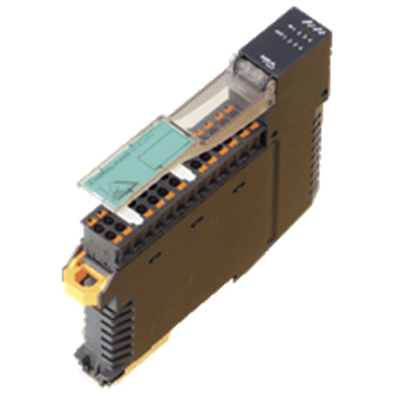
AS-Interface sensor/actuator module VAA-4E4A-KE5-ZEJQ/R VAA-4E4A-KE5-ZEJQ/R Housing with push-in connection technology and mechanically coded terminal blocks Housing width 19 mm, installation in the switch cabinet on DIN mounting rail Selectable supply to the sensors: External or from the module Function display for bus, internal sensor supply, inputs, and outputs AS-Interface sensor/actuator module VAA-4E4A-KE5-ZEJQ/R VAA-4E4A-KE5-ZEJQ/R Housing with push-in connection technology and mechanically coded terminal blocks Housing width 19 mm, installation in the switch cabinet on DIN mounting rail Selectable supply to the sensors: External or from the module Function display for bus, internal sensor supply, inputs, and outputs
La imagen del producto es solo para fines ilustrativos.
El país de origen, el código del HS y la descripción son proporcionados por el fabricante y pueden estar sujetos a cambios sin previo aviso. Por esta razón, PLC-City no puede ser responsable de las discrepancias.


 y muchos más
Aceptamos muchos métodos de pago: Transferencia bancaria (SEPA, ACH), Tarjetas de débito/ crédito (Mastercard, VISA, American Express, Diners Club, Discover, JCB, UnionPay), PayPal, ApplePay, GooglePay, enlace por Stripe, Cartes Bancaires, Alipay, Bancontact, blik, eps, giropay Deal, Przelewy24, WhateCPay.
Más información sobre nuestros métodos de pago
Este producto está cubierto por una garantía 12 Meses válida para defectos de fabricación o mal funcionamiento. La garantía no cubre los daños causados por un uso inadecuado o daños accidentales.
Más información sobre nuestra garantía
Las devoluciones están sujetas a autorización previa y se reembolsarán con un crédito en tienda. Se excluyen los artículos en backorder.

 y muchos más
Aceptamos muchos métodos de pago: Transferencia bancaria (SEPA, ACH), Tarjetas de débito/ crédito (Mastercard, VISA, American Express, Diners Club, Discover, JCB, UnionPay), PayPal, ApplePay, GooglePay, enlace por Stripe, Cartes Bancaires, Alipay, Bancontact, blik, eps, giropay Deal, Przelewy24, WhateCPay.
Más información sobre nuestros métodos de pago
Este producto está cubierto por una garantía 12 Meses válida para defectos de fabricación o mal funcionamiento. La garantía no cubre los daños causados por un uso inadecuado o daños accidentales.
Más información sobre nuestra garantía
Las devoluciones están sujetas a autorización previa y se reembolsarán con un crédito en tienda. Se excluyen los artículos en backorder.