 IT
USD
IT
USD
-
MenùTornare
-
Brands
-
- Tecnologie per :
-
Industria
-
-
Edifici
-
-
Elettrificazione
-
-
Utensili
-
- Contattaci
- Chi Siamo
- Promo
-
PLC-City
Via Circumvallazione esterna 12
80025 Casandrino NA
Italia
VBA-4E4A-KE-ZE/R PEPPERL+FUCHS - Part number: 200913
PEPPERL+FUCHS
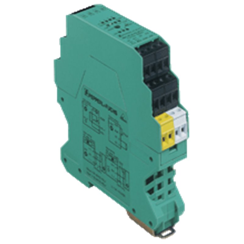
AS-Interface sensor/actuator module VBA-4E4A-KE-ZE/R VBA-4E4A-KE-ZE/R Housing with removable, mechanical and color coded terminals Communication monitoring Inputs for 2- and 3-wire sensors Isolated relay output Addressing jack Selectable supply to the sensors: External or from the module Function display for bus, internal sensor supply, inputs, and outputs AS-Interface sensor/actuator module VBA-4E4A-KE-ZE/R VBA-4E4A-KE-ZE/R Housing with removable, mechanical and color coded terminals Communication monitoring Inputs for 2- and 3-wire sensors Isolated relay output Addressing jack Selectable supply to the sensors: External or from the module Function display for bus, internal sensor supply, inputs, and outputs
L'immagine del prodotto è solo a scopo illustrativo.
Il paese di origine, il codice HS e la descrizione sono forniti dal produttore e possono essere soggetti a modifiche senza preavviso. Per questo motivo, PLC-City non può essere ritenuta responsabile di eventuali discrepanze.
Accettiamo molti metodi di pagamento: Bonifico bancario (SEPA, ACH), Carte di debito/credito (Mastercard, VISA, American Express, Diners Club, Discover, JCB, UnionPay), PayPal, ApplePay, GooglePay, link by Stripe, Cartes Bancaires, Alipay, Bancontact, blik, eps, giropay iDeal, Przelewy24, WeChatPay.
Maggiori informazioni sui nostri metodi di pagamento
Questo prodotto è coperto da una garanzia di 12 Mesi, valida per difetti di fabbricazione o malfunzionamenti. La garanzia non copre danni causati da uso improprio o danni accidentali.
Maggiori informazioni sulla nostra garanzia
È possibile effettuare il reso previa autorizzazione e ottenere un credito, escluso per il backorder.