 RU
USD
RU
USD
-
МенюНазад
-
бренды
-
- Технологии для :
-
Промышленность
-
-
- Automation
- Motors & Drives
- Safety
-
Sensors
- Accessories/spare parts for industrial sensors
- Detection
- distance
- scanners
- RFID
-
process
- Liquid flow sensor
- Liquid flow meter
- Temperature transformer
- Pressure switches
- Датчик перепада давления
- Преобразователь давления
- Погружной пассивный датчик температуры
- Датчик уровня жидкости
- Радарный датчик уровня
- Датчик вибрации
- Ультразвуковой уровнемер
- Емкостный датчик уровня
- Измерительные приборы температуры и климата
- Температурные зонды
- Current value transformer
- Isolation amplifier
- Machine vision system (MVS)
- rotary encoder
- Connect
- Signal Cables
- Weighing
- Valves & Controls
-
Industrial Plugs & Sockets
- Panel-mounted CEE socket outlet (IEC 60309)
- CEE coupling (IEC 60309)
- CEE plug (IEC 60309)
- CEE socket outlet combination (IEC 60309)
- CEE appliance inlet (IEC 60309)
- CEE socket outlet (IEC 60309)
- CEE socket outlet, disconnectable, with fuse (IEC 60309)
- Взрывозащищенная розетка CEE (IEC 60309)
- Аксессуары/запчасти для вилок и розеток CEE (IEC 60309)
- Аксессуары и запасные части для измерительных и испытательных приборов
- Мониторинг энергии
-
-
-
Здания
-
-
- Green Power
- HVAC - Climatisation
- Lighting
- Monitor & Networking
- e-Mobility
-
Automation - Bus Systems
-
Control Elements
- Analogue input for bus system
- Basic module for bus system
- Binary input for bus system
- Central device for bus system
- Controller for home automation systems
- Display for bus system
- I/O device for bus system
- Logic component for bus system
- Signalling and operation panel for bus system
- Light control unit for bus system
- Комнатный регулятор температуры для шинной системы
- Sensors
- Actuators
- Bus Communications
- Programming
- Others
-
Control Elements
-
Domestic switching devices
- Socket outlet combinations
- Cover frames for domestic switching devices
- Mounting for labelling material
- Plug adapters
- Socket outlets
- Plugs with protective contact
- Inserts/covers for communication technology
- Installation switches
- Movement sensors/presence detectors complete
- Push buttons
- Control elements/cover plates for domestic switching devices
- USB power supplies
- Sensor elements for movement sensor
- Блоки распределения питания (PDU)
- Energy consumption indication
- Emergency call system devices
- Устройства систем клинической установки
- Pluggable building installation systems
-
-
-
Электрика
-
-
- Cables
-
Installation
- Saddle clamps (pipe/cable)
- Аксессуары для встраиваемых и распределительных коробок
-
Аксессуары для кабелей и трубок
- Втулка кабельного ввода
- Заглушка для кабельного ввода
- Кабельные стяжки
- Кабельный ввод
- Контргайка для кабельного ввода
- Крепежные зажимы
- Крепления для кабельных стяжек
- Муфта для монтажных труб
- Отводы для монтажных труб
- Резьбовая втулка
- Увеличительное/редукционное кольцо
- Уплотнительные кольца
- Уплотнительный зажим для кабеля
-
Изоляция и соединение
- Аксессуары/запчасти для монтажных и соединительных материалов
- Вставная клемма
- Изоляционный шланг для кабеля
- Кабельный наконечник-гильза
- Клейкая лента
- Обжимной кабельный наконечник для алюминиевых проводников
- Обжимной кабельный наконечник для медных проводников
- Ответвительная муфта (комплект)
- Соединение для экранированных проводов
- Соединитель для светильника
- Термоусадочная трубка
- Формованные термоусаживаемые элементы / Breakout boot
- Клемма для светильника
- Металлические монтажные трубы
- Перфорированные кабельные каналы
- Распределительные коробки
-
Системы защитных шлангов
- Гофрированный пластиковый шланг
- Защитный металлический шланг
- Защитный пластиковый шланг
- Концевая втулка для защитного шланга
- Оплетённый шланг
- Резьбовое соединение для гофрированного пластикового шланга
- Резьбовое соединение для защитного металлического шланга
- Резьбовое соединение для защитного пластикового шланга
- Соединитель для гофрированных пластиковых шлангов
- Уплотнение для резьбового соединения шланга
- Шланг для кабельного жгута
- Хомуты для труб
-
Low Voltage
-
Cabinets & Enclosures
- Base/base element (enclosure/cabinet)
- Clima Control
- Door/operating panel (enclosure/cabinet)
- Electronic enclosure
- Empty cabinet
-
Energy distribution systems
- Accessories/spare parts for busbar trunks
- Accessories/spare parts for busbars
- Busbar couplers
- Busbar supports
- Busbar trunk units
- Cover caps for rail terminal bar
- Distributor assembly miniature circuit breakers (MCB)
- Distributor assembly terminal blocks
- Feed units for busbar trunk
- Main line branch terminals
- Meter cabinets equipped
- Mounting plates for distribution board
- Mounting rails
- Mounting systems for busbar trunk
- Phase barrier plates
- Tap off units for busbar trunk
- Крышки для распределительных щитов
- Малый распределительный щит
- Панель для распределительного щита
- Explosion proof enclosure/housing
- Front panel (enclosure/cabinet)
- Keys for enclosures/cabinets
- Lock systems for enclosure/cabinet
- Mounting accessories (enclosure/cabinet)
- Network cabinet
- Network/server enclosure
-
Circuit Breakers
- Auxiliary contact block
- Busbar adapters
- Device circuit breaker
- Earth leakage circuit breaker
- Fuse switch disconnector
- Fuses
- Main line circuit breaker
- Miniature circuit breaker (MCB)
- Off-load switches
-
Power Circuit Breakers
- Chassis part power circuit breaker
- Door coupling handles
- Handle for power circuit breaker
- Modification set for power circuit breaker
- Motor operator for power circuit-breaker
- Phase separation plate for power circuit breaker
- Shunt release (for power circuit breaker)
- Switch spool for power circuit breaker
- Trip block for power circuit-breaker
- Under voltage coil
- Wiring set for power circuit breaker
- Residual current circuit breaker (RCCB)
- Surge protection device for power supply systems
- Trip indicator
-
command devices (Buttons, selectors, indicators)
- Accessories/spare parts for command devices
- Accessories/spare parts for emergency stop pull cord switch
- Acoustic indicator
- Adapter for command devices
- Buttons
- Control circuit devices combination in enclosure
- Control switch, Joystick
- Emergency stop complete
- Emergency stop pull cord switch
- Enclosure for control circuit devices
- Foot switch
- Legend plate for control circuit devices
- Potentiometer for command devices
- Protective cap for command devices
- Selectors
- Signal towers
- Text plate for command devices
- Two-hand control device
- Световые индикаторы / пилотные лампы
- Световые индикаторы / сигнальные лампы
- Contactors
- Filters for low-voltage
- Low Voltage Accessories
-
Motor start & protection
- Accessories/spare parts for electronic motor control and protection device
- Electronic overload relay
- Extension module for motor management device
- Motor management device
- Motor protection circuit-breaker
- Motor starter/motor starter combination
- Operator panel for Motor management device
- Soft starter
- Thermal overload relay
- Power supply
-
Relays
- (Fill) level monitoring relay
- Accessories/spare parts for switching relay
- Current monitoring relay
- Latching relay
- Optocoupler
- Relay socket
- Relays for thermistor protection (PTC)
- Residual current monitoring relay
- Residual current monitoring relay
- Solid state relay
- Speed-/standstill monitoring relay
- Speed-/standstill monitoring relay
- Switching relay
- Temperature monitoring relay
- Timer blocks
- Timer relay
- Voltage monitoring relay
- Установочные реле
- Surge protection module
- Switch disconnector (low voltage)
-
Terminal blocks
- (Knife) disconnect terminal block
- Accessories/spare parts for terminals
- Component plug terminal block
- Component terminal block
- Cross-connector for terminal block
- End bracket for terminal block
- Endplate and partition plate for terminal block
- Feed-through terminal block
- Fuse terminal block
- Ground terminal block
- Labelling for terminal block
- Multi level installation terminal block
- Sensor/actuator terminal block
- Shield connection clamp
- Single- and multi-pole terminal strip
- Terminal block connector
- Test plug for terminal blocks
- Transformers & coils
- Адаптеры для DIN-рейки
- Батареи и батарейные модули
- Защита от перенапряжений для линий данных/сигнала
- Распределительные щиты ASC для строительных площадок
- Силовые конденсаторы
-
Cabinets & Enclosures
- Marking
- Optical and acoustic signalling
- UPS
-
-
-
Инструменты
-
- Свяжитесь с нами
- О нас
- Промо
-
PLC-City
Via Circumvallazione esterna 12
80025 Casandrino NA
Италия
-
МенюНазад
-
бренды
-
- Технологии для :
-
Промышленность
-
-
- Automation
- Motors & Drives
- Safety
-
Sensors
- Accessories/spare parts for industrial sensors
- Detection
- distance
- scanners
- RFID
-
process
- Liquid flow sensor
- Liquid flow meter
- Temperature transformer
- Pressure switches
- Датчик перепада давления
- Преобразователь давления
- Погружной пассивный датчик температуры
- Датчик уровня жидкости
- Радарный датчик уровня
- Датчик вибрации
- Ультразвуковой уровнемер
- Емкостный датчик уровня
- Измерительные приборы температуры и климата
- Температурные зонды
- Current value transformer
- Isolation amplifier
- Machine vision system (MVS)
- rotary encoder
- Connect
- Signal Cables
- Weighing
- Valves & Controls
-
Industrial Plugs & Sockets
- Panel-mounted CEE socket outlet (IEC 60309)
- CEE coupling (IEC 60309)
- CEE plug (IEC 60309)
- CEE socket outlet combination (IEC 60309)
- CEE appliance inlet (IEC 60309)
- CEE socket outlet (IEC 60309)
- CEE socket outlet, disconnectable, with fuse (IEC 60309)
- Взрывозащищенная розетка CEE (IEC 60309)
- Аксессуары/запчасти для вилок и розеток CEE (IEC 60309)
- Аксессуары и запасные части для измерительных и испытательных приборов
- Мониторинг энергии
-
-
-
Здания
-
-
- Green Power
- HVAC - Climatisation
- Lighting
- Monitor & Networking
- e-Mobility
-
Automation - Bus Systems
-
Control Elements
- Analogue input for bus system
- Basic module for bus system
- Binary input for bus system
- Central device for bus system
- Controller for home automation systems
- Display for bus system
- I/O device for bus system
- Logic component for bus system
- Signalling and operation panel for bus system
- Light control unit for bus system
- Комнатный регулятор температуры для шинной системы
- Sensors
- Actuators
- Bus Communications
- Programming
- Others
-
Control Elements
-
Domestic switching devices
- Socket outlet combinations
- Cover frames for domestic switching devices
- Mounting for labelling material
- Plug adapters
- Socket outlets
- Plugs with protective contact
- Inserts/covers for communication technology
- Installation switches
- Movement sensors/presence detectors complete
- Push buttons
- Control elements/cover plates for domestic switching devices
- USB power supplies
- Sensor elements for movement sensor
- Блоки распределения питания (PDU)
- Energy consumption indication
- Emergency call system devices
- Устройства систем клинической установки
- Pluggable building installation systems
-
-
-
Электрика
-
-
- Cables
-
Installation
- Saddle clamps (pipe/cable)
- Аксессуары для встраиваемых и распределительных коробок
-
Аксессуары для кабелей и трубок
- Втулка кабельного ввода
- Заглушка для кабельного ввода
- Кабельные стяжки
- Кабельный ввод
- Контргайка для кабельного ввода
- Крепежные зажимы
- Крепления для кабельных стяжек
- Муфта для монтажных труб
- Отводы для монтажных труб
- Резьбовая втулка
- Увеличительное/редукционное кольцо
- Уплотнительные кольца
- Уплотнительный зажим для кабеля
-
Изоляция и соединение
- Аксессуары/запчасти для монтажных и соединительных материалов
- Вставная клемма
- Изоляционный шланг для кабеля
- Кабельный наконечник-гильза
- Клейкая лента
- Обжимной кабельный наконечник для алюминиевых проводников
- Обжимной кабельный наконечник для медных проводников
- Ответвительная муфта (комплект)
- Соединение для экранированных проводов
- Соединитель для светильника
- Термоусадочная трубка
- Формованные термоусаживаемые элементы / Breakout boot
- Клемма для светильника
- Металлические монтажные трубы
- Перфорированные кабельные каналы
- Распределительные коробки
-
Системы защитных шлангов
- Гофрированный пластиковый шланг
- Защитный металлический шланг
- Защитный пластиковый шланг
- Концевая втулка для защитного шланга
- Оплетённый шланг
- Резьбовое соединение для гофрированного пластикового шланга
- Резьбовое соединение для защитного металлического шланга
- Резьбовое соединение для защитного пластикового шланга
- Соединитель для гофрированных пластиковых шлангов
- Уплотнение для резьбового соединения шланга
- Шланг для кабельного жгута
- Хомуты для труб
-
Low Voltage
-
Cabinets & Enclosures
- Base/base element (enclosure/cabinet)
- Clima Control
- Door/operating panel (enclosure/cabinet)
- Electronic enclosure
- Empty cabinet
-
Energy distribution systems
- Accessories/spare parts for busbar trunks
- Accessories/spare parts for busbars
- Busbar couplers
- Busbar supports
- Busbar trunk units
- Cover caps for rail terminal bar
- Distributor assembly miniature circuit breakers (MCB)
- Distributor assembly terminal blocks
- Feed units for busbar trunk
- Main line branch terminals
- Meter cabinets equipped
- Mounting plates for distribution board
- Mounting rails
- Mounting systems for busbar trunk
- Phase barrier plates
- Tap off units for busbar trunk
- Крышки для распределительных щитов
- Малый распределительный щит
- Панель для распределительного щита
- Explosion proof enclosure/housing
- Front panel (enclosure/cabinet)
- Keys for enclosures/cabinets
- Lock systems for enclosure/cabinet
- Mounting accessories (enclosure/cabinet)
- Network cabinet
- Network/server enclosure
-
Circuit Breakers
- Auxiliary contact block
- Busbar adapters
- Device circuit breaker
- Earth leakage circuit breaker
- Fuse switch disconnector
- Fuses
- Main line circuit breaker
- Miniature circuit breaker (MCB)
- Off-load switches
-
Power Circuit Breakers
- Chassis part power circuit breaker
- Door coupling handles
- Handle for power circuit breaker
- Modification set for power circuit breaker
- Motor operator for power circuit-breaker
- Phase separation plate for power circuit breaker
- Shunt release (for power circuit breaker)
- Switch spool for power circuit breaker
- Trip block for power circuit-breaker
- Under voltage coil
- Wiring set for power circuit breaker
- Residual current circuit breaker (RCCB)
- Surge protection device for power supply systems
- Trip indicator
-
command devices (Buttons, selectors, indicators)
- Accessories/spare parts for command devices
- Accessories/spare parts for emergency stop pull cord switch
- Acoustic indicator
- Adapter for command devices
- Buttons
- Control circuit devices combination in enclosure
- Control switch, Joystick
- Emergency stop complete
- Emergency stop pull cord switch
- Enclosure for control circuit devices
- Foot switch
- Legend plate for control circuit devices
- Potentiometer for command devices
- Protective cap for command devices
- Selectors
- Signal towers
- Text plate for command devices
- Two-hand control device
- Световые индикаторы / пилотные лампы
- Световые индикаторы / сигнальные лампы
- Contactors
- Filters for low-voltage
- Low Voltage Accessories
-
Motor start & protection
- Accessories/spare parts for electronic motor control and protection device
- Electronic overload relay
- Extension module for motor management device
- Motor management device
- Motor protection circuit-breaker
- Motor starter/motor starter combination
- Operator panel for Motor management device
- Soft starter
- Thermal overload relay
- Power supply
-
Relays
- (Fill) level monitoring relay
- Accessories/spare parts for switching relay
- Current monitoring relay
- Latching relay
- Optocoupler
- Relay socket
- Relays for thermistor protection (PTC)
- Residual current monitoring relay
- Residual current monitoring relay
- Solid state relay
- Speed-/standstill monitoring relay
- Speed-/standstill monitoring relay
- Switching relay
- Temperature monitoring relay
- Timer blocks
- Timer relay
- Voltage monitoring relay
- Установочные реле
- Surge protection module
- Switch disconnector (low voltage)
-
Terminal blocks
- (Knife) disconnect terminal block
- Accessories/spare parts for terminals
- Component plug terminal block
- Component terminal block
- Cross-connector for terminal block
- End bracket for terminal block
- Endplate and partition plate for terminal block
- Feed-through terminal block
- Fuse terminal block
- Ground terminal block
- Labelling for terminal block
- Multi level installation terminal block
- Sensor/actuator terminal block
- Shield connection clamp
- Single- and multi-pole terminal strip
- Terminal block connector
- Test plug for terminal blocks
- Transformers & coils
- Адаптеры для DIN-рейки
- Батареи и батарейные модули
- Защита от перенапряжений для линий данных/сигнала
- Распределительные щиты ASC для строительных площадок
- Силовые конденсаторы
-
Cabinets & Enclosures
- Marking
- Optical and acoustic signalling
- UPS
-
-
-
Инструменты
-
- Свяжитесь с нами
- О нас
- Промо
VAA-2EA-G2-ZA/EA2 PEPPERL+FUCHS - Part number: 187747
PEPPERL+FUCHS
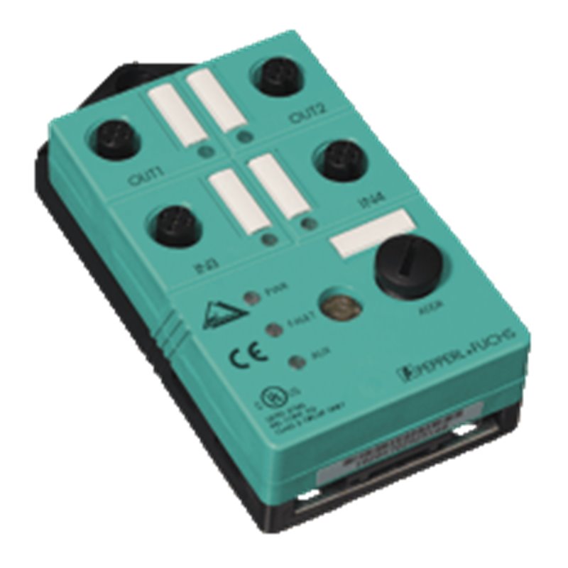
Изображение продукта предназначено только для иллюстрации.
Страна происхождения, код ГС и описание предоставлены производителем и могут быть изменены без предварительного уведомления. По этой причине PLC-City не может нести ответственность за любые расхождения.
Мы принимаем много способов оплаты: Банковский перевод (SEPA, ACH), Дебетовые/ Кредитные карты (Mastercard, VISA, American Express, Diners Club, Discover, JCB, UnionPay), PayPal, ApplePay, GooglePay, Link by Stripe, Cartes Bancaires, Alipay, Banbancontact, blik, eps, giropay, Przelewy24, WhateCeCPay.
Подробнее о наших методах оплаты
Этот продукт покрыт гарантией 12 месяцы, действительный для производственных дефектов или неисправностей. Гарантия не покрывает ущерб, вызванный неправильным использованием или случайным повреждением.
Узнайте больше о нашей гарантии
Возврат осуществляется только с предварительного одобрения и компенсируется магазинным кредитом. Товары по предзаказу не подлежат возврату.