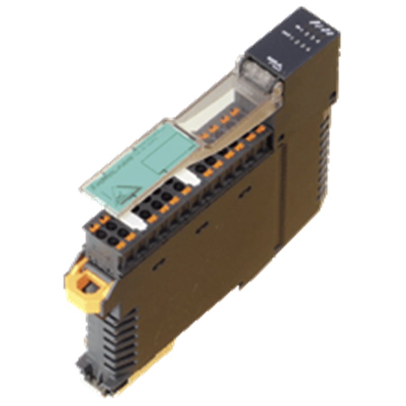
VBA-4E4A-KE5-ZEJQ/R PEPPERL+FUCHS - Part number: 263814
нет в наличии - Дозаказ
Заказать у производителя
310,91 USD

Импортные налоги не включены

Вы должны авторизоваться

VBA-4E4A-KE5-ZEJQ/R PEPPERL+FUCHS - Part number: 263814

MPNs 263814, PEP263814, VBA-4E4A-KE5-ZEJQ/R
кода ГС 85371091
Weight 0.13 kg

Изображение продукта предназначено только для иллюстрации.
Страна происхождения, код ГС и описание предоставлены производителем и могут быть изменены без предварительного уведомления. По этой причине PLC-City не может нести ответственность за любые расхождения.
Продано PLC-CITY® и отправлено из Италии

Мы принимаем много способов оплаты: Банковский перевод (SEPA, ACH), Дебетовые/ Кредитные карты (Mastercard, VISA, American Express, Diners Club, Discover, JCB, UnionPay), PayPal, ApplePay, GooglePay, Link by Stripe, Cartes Bancaires, Alipay, Banbancontact, blik, eps, giropay, Przelewy24, WhateCeCPay.
Подробнее о наших методах оплаты

Этот продукт покрыт гарантией 12 месяцы, действительный для производственных дефектов или неисправностей. Гарантия не покрывает ущерб, вызванный неправильным использованием или случайным повреждением.
Узнайте больше о нашей гарантии

Возврат осуществляется только с предварительного одобрения и компенсируется магазинным кредитом. Товары по предзаказу не подлежат возврату.

Просмотреть нашу политику возврата

310,91 USD

Импортные налоги не включены

Вы должны авторизоваться
Продано PLC-CITY® и отправлено из Италии
Мы являемся специализированным партнером PEPPERL+FUCHS
Бесплатная экспресс-доставка в США
Loader...
Просмотреть все услуги доставки
Запрашивать предложение, чтобы знать дату поставки

Мы принимаем много способов оплаты: Банковский перевод (SEPA, ACH), Дебетовые/ Кредитные карты (Mastercard, VISA, American Express, Diners Club, Discover, JCB, UnionPay), PayPal, ApplePay, GooglePay, Link by Stripe, Cartes Bancaires, Alipay, Banbancontact, blik, eps, giropay, Przelewy24, WhateCeCPay.
Подробнее о наших методах оплаты

Этот продукт покрыт гарантией 12 месяцы, действительный для производственных дефектов или неисправностей. Гарантия не покрывает ущерб, вызванный неправильным использованием или случайным повреждением.
Узнайте больше о нашей гарантии

Возврат осуществляется только с предварительного одобрения и компенсируется магазинным кредитом. Товары по предзаказу не подлежат возврату.

Просмотреть нашу политику возврата

Получите свою персонализированную цитату сейчас

Специальный представитель поможет вам предложить лучшие цены и сроки доставки.

Вы должны авторизоваться

информацию о продукте

Описание

Datasheet excerpt: Technical data of  VBA-4E4A-KE5-ZEJQ/R Product Description Cabinet module4 inputs and 4 relay outputs General specifications Node typeA/B node AS-Interface specificationV3.0 Required master specification≥ V3.0 UL File NumberE223772 MTBF224 a Indicators/operating means LED FAULTFault display; Red LEDred: Communication fault or address is 0red, flashing: Overload, internal input supply LED INTInternal input supply active; LED green LED PWRAS-Interface voltage; green LEDgreen: voltage OKflashing green: address 0 LED INswitching state (input); 4 LED yellow LED OUTSwitching state (output); 4 LED yellow Electrical specifications Auxiliary voltage (input)12 ... 30 V DC PELV Rated operating voltage26.5 ... 31.6 V from AS-Interface Rated operating current≤ 35 mA (without sensors) / max. 230 mA Surge protectionO1 ... O4: Over voltage category IIUEXT, Ue: overvoltage category II, safe isolated power supplies (PELV) Input Number/Type4 inputs for 3-wire sensors (PNP), DC Supplyfrom AS-Interface (switch position INT, default settings) or external UEXT (switch position EXT) Voltage21 ... 31 V DC (INT) Current loading capacity≤ 150 mA, overload- and short-circuit protected (INT) Input current≤ 5.6 mA (max.) Switching pointaccording to DIN EN 61131-2 (type 1) 0 (unattenuated)≤ 0.5 mA 1 (attenuated)≥ 2 mA Signal delay< 1 ms (input/AS-Interface) Output Number/Type4 relay outputs, normally open Supplynone Nominal load Per contact2 A/30 VDC; 2 A/250 VAC For more information, see the "Galvanic Isolation" section Per module8 A Control circuit≤ 11 mA per relay (from AS-Interface) Switching delay< 10 ms (AS-Interface/contact) Usage categoryDC-13 and AC-14 Switching Mechanical5 x 107 Electrical2 x 105 (250 VAC, 2 A, cos φ = 0.4) Galvanic isolation Input/Outputsafe isolation, Rated insulation voltage 252 Veff Input/AS-InterfaceSwitch position INT: None Switch setting EXT: safe isolation, rated insulation voltage 92 Veff Output/OutputBasic insulation, rated insulation voltage 250 Veff, in phase Output/AS-Interfacesafe isolation, Rated insulation voltage 252 Veff Directive conformity Electromagnetic compatibility Directive 2014/30/EUEN 62026-2:2013 EN 61000-6-2:2005, EN 61000-6-4:2007 Low voltage Directive 2006/95/ECEN 60664-1:2007 Standard conformity Galvanic isolationEN 60664-1:2007 Degree of protectionEN 60529:2000 Fieldbus standardEN 62026-2:2013 Electrical safetyIEC 61140:2009 InputEN 61131-2:2004 Emitted interferenceEN 61000-6-4:2007 AS-InterfaceEN 62026-2:2013 Noise immunityEN 61000-6-2:2005, EN 61326-1:2006, EN 62026-2:2013 Programming instructions ProfileS-7.A.7 IO code7 ID codeA ID1 code7 ID2 code7 Data bits (function via AS-Interface) input output D0 IN1 O1 D1 IN2 O2 D2 IN3 O3 D3 IN4 O4 Parameter bits (programmable via AS-i)function P0Communication monitoringP0 = 0 monitoring = off, the outputs maintain the status if communication failsP0 = 1 monitoring = on, i.e. if communication fails, the outputs are deenergised (default settings) P1Input filterP1 = 0 input filter on, pulse suppression ≤ 2 msP1 = 1 input filter off (default settings) P2Synchronous modeP2 = 0 synchronous mode onP2 = 1 synchronous mode off (default settings) P3not used Ambient conditions Ambient temperature-25 ... 60 °C (-13 ... 140 °F) Storage temperature-25 ... 85 °C (-13 ... 185 °F) Relative humidity85 % , noncondensing Climatic conditionsFor indoor use only Altitude≤ 2000 m above MSL Shock and impact resistance15 g, 11 ms in 6 spatial directions, 3 shocks 10 g, 16 ms in 6 spatial directions, 1000 shocks Vibration resistance0.35 mm 10 ... 57 Hz , 5 g 57 ... 150 Hz, 20 cycles Pollution degree2 Mechanical specifications Degree of protectionIP20 Installation in an enclosure with a minimum protection class of IP54 required ConnectionRemovable push-in terminalsrated connection capacity:rigid: 0.20 mm2 ... 1.5 mm2flexible (without wire end ferrule): 0.20 mm2 ... 2.5 mm2flexible (with wire end ferrule): 0.25 mm2 ... 1.5 mm2 Material HousingPA 66-FR Mass125 g MountingDIN mounting rail Classifications SystemClasscode ECLASS 11.027242604 ECLASS 10.0.127242604 ECLASS 9.027242604 ECLASS 8.027242604 ECLASS 5.127242604 ETIM 8.0EC001599 ETIM 7.0EC001599 ETIM 6.0EC001599 ETIM 5.0EC001599 UNSPSC 12.139121535 Datasheet excerpt: Technical data of  VBA-4E4A-KE5-ZEJQ/R Product Description Cabinet module4 inputs and 4 relay outputs General specifications Node typeA/B node AS-Interface specificationV3.0 Required master specification≥ V3.0 UL File NumberE223772 MTBF224 a Indicators/operating means LED FAULTFault display; Red LEDred: Communication fault or address is 0red, flashing: Overload, internal input supply LED INTInternal input supply active; LED green LED PWRAS-Interface voltage; green LEDgreen: voltage OKflashing green: address 0 LED INswitching state (input); 4 LED yellow LED OUTSwitching state (output); 4 LED yellow Electrical specifications Auxiliary voltage (input)12 ... 30 V DC PELV Rated operating voltage26.5 ... 31.6 V from AS-Interface Rated operating current≤ 35 mA (without sensors) / max. 230 mA Surge protectionO1 ... O4: Over voltage category IIUEXT, Ue: overvoltage category II, safe isolated power supplies (PELV) Input Number/Type4 inputs for 3-wire sensors (PNP), DC Supplyfrom AS-Interface (switch position INT, default settings) or external UEXT (switch position EXT) Voltage21 ... 31 V DC (INT) Current loading capacity≤ 150 mA, overload- and short-circuit protected (INT) Input current≤ 5.6 mA (max.) Switching pointaccording to DIN EN 61131-2 (type 1) 0 (unattenuated)≤ 0.5 mA 1 (attenuated)≥ 2 mA Signal delay< 1 ms (input/AS-Interface) Output Number/Type4 relay outputs, normally open Supplynone Nominal load Per contact2 A/30 VDC; 2 A/250 VAC For more information, see the "Galvanic Isolation" section Per module8 A Control circuit≤ 11 mA per relay (from AS-Interface) Switching delay< 10 ms (AS-Interface/contact) Usage categoryDC-13 and AC-14 Switching Mechanical5 x 107 Electrical2 x 105 (250 VAC, 2 A, cos φ = 0.4) Galvanic isolation Input/Outputsafe isolation, Rated insulation voltage 252 Veff Input/AS-InterfaceSwitch position INT: None Switch setting EXT: safe isolation, rated insulation voltage 92 Veff Output/OutputBasic insulation, rated insulation voltage 250 Veff, in phase Output/AS-Interfacesafe isolation, Rated insulation voltage 252 Veff Directive conformity Electromagnetic compatibility Directive 2014/30/EUEN 62026-2:2013 EN 61000-6-2:2005, EN 61000-6-4:2007 Low voltage Directive 2006/95/ECEN 60664-1:2007 Standard conformity Galvanic isolationEN 60664-1:2007 Degree of protectionEN 60529:2000 Fieldbus standardEN 62026-2:2013 Electrical safetyIEC 61140:2009 InputEN 61131-2:2004 Emitted interferenceEN 61000-6-4:2007 AS-InterfaceEN 62026-2:2013 Noise immunityEN 61000-6-2:2005, EN 61326-1:2006, EN 62026-2:2013 Programming instructions ProfileS-7.A.7 IO code7 ID codeA ID1 code7 ID2 code7 Data bits (function via AS-Interface) input output D0 IN1 O1 D1 IN2 O2 D2 IN3 O3 D3 IN4 O4 Parameter bits (programmable via AS-i)function P0Communication monitoringP0 = 0 monitoring = off, the outputs maintain the status if communication failsP0 = 1 monitoring = on, i.e. if communication fails, the outputs are deenergised (default settings) P1Input filterP1 = 0 input filter on, pulse suppression ≤ 2 msP1 = 1 input filter off (default settings) P2Synchronous modeP2 = 0 synchronous mode onP2 = 1 synchronous mode off (default settings) P3not used Ambient conditions Ambient temperature-25 ... 60 °C (-13 ... 140 °F) Storage temperature-25 ... 85 °C (-13 ... 185 °F) Relative humidity85 % , noncondensing Climatic conditionsFor indoor use only Altitude≤ 2000 m above MSL Shock and impact resistance15 g, 11 ms in 6 spatial directions, 3 shocks 10 g, 16 ms in 6 spatial directions, 1000 shocks Vibration resistance0.35 mm 10 ... 57 Hz , 5 g 57 ... 150 Hz, 20 cycles Pollution degree2 Mechanical specifications Degree of protectionIP20 Installation in an enclosure with a minimum protection class of IP54 required ConnectionRemovable push-in terminalsrated connection capacity:rigid: 0.20 mm2 ... 1.5 mm2flexible (without wire end ferrule): 0.20 mm2 ... 2.5 mm2flexible (with wire end ferrule): 0.25 mm2 ... 1.5 mm2 Material HousingPA 66-FR Mass125 g MountingDIN mounting rail Classifications SystemClasscode ECLASS 11.027242604 ECLASS 10.0.127242604 ECLASS 9.027242604 ECLASS 8.027242604 ECLASS 5.127242604 ETIM 8.0EC001599 ETIM 7.0EC001599 ETIM 6.0EC001599 ETIM 5.0EC001599 UNSPSC 12.139121535

Отзывы о нашей компании