订单满150欧元(最多10公斤)可享欧洲、美国和加拿大免费快递配送。
info
 ZH
USD
ZH
USD
探索
-
Menu返回
-
品牌
-
- Technologies for:
-
Industry
-
-
Building
-
-
Electrification
-
-
- Cables
- Installation
-
Low Voltage
-
Cabinets & Enclosures
- Base/base element (enclosure/cabinet)
- Clima Control
- Door/operating panel (enclosure/cabinet)
- Electronic enclosure
- Empty cabinet
-
Energy distribution systems
- Accessories/spare parts for busbar trunks
- Accessories/spare parts for busbars
- Busbar couplers
- Busbar supports
- Busbar trunk units
- Cover caps for rail terminal bar
- Distributor assembly miniature circuit breakers (MCB)
- Distributor assembly terminal blocks
- Feed units for busbar trunk
- Main line branch terminals
- Meter cabinets equipped
- Mounting plates for distribution board
- Mounting rails
- Mounting systems for busbar trunk
- Phase barrier plates
- Tap off units for busbar trunk
- 小型配电箱
- 配电板面板
- 配电箱盖板
- Explosion proof enclosure/housing
- Front panel (enclosure/cabinet)
- Keys for enclosures/cabinets
- Lock systems for enclosure/cabinet
- Mounting accessories (enclosure/cabinet)
- Network cabinet
- Network/server enclosure
-
Circuit Breakers
- Auxiliary contact block
- Busbar adapters
- Device circuit breaker
- Earth leakage circuit breaker
- Fuse switch disconnector
- Fuses
- Main line circuit breaker
- Miniature circuit breaker (MCB)
- Off-load switches
-
Power Circuit Breakers
- Chassis part power circuit breaker
- Door coupling handles
- Handle for power circuit breaker
- Modification set for power circuit breaker
- Motor operator for power circuit-breaker
- Phase separation plate for power circuit breaker
- Shunt release (for power circuit breaker)
- Switch spool for power circuit breaker
- Trip block for power circuit-breaker
- Under voltage coil
- Wiring set for power circuit breaker
- Residual current circuit breaker (RCCB)
- Surge protection device for power supply systems
- Trip indicator
-
command devices (Buttons, selectors, indicators)
- Accessories/spare parts for command devices
- Accessories/spare parts for emergency stop pull cord switch
- Acoustic indicator
- Adapter for command devices
- Buttons
- Control circuit devices combination in enclosure
- Control switch, Joystick
- Emergency stop complete
- Emergency stop pull cord switch
- Enclosure for control circuit devices
- Foot switch
- Legend plate for control circuit devices
- Potentiometer for command devices
- Protective cap for command devices
- Selectors
- Signal towers
- Text plate for command devices
- Two-hand control device
- 指示灯 / 信号灯
- 指示灯 / 信号灯
- Contactors
- DIN 导轨适配器
- Filters for low-voltage
- Low Voltage Accessories
-
Motor start & protection
- Accessories/spare parts for electronic motor control and protection device
- Electronic overload relay
- Extension module for motor management device
- Motor management device
- Motor protection circuit-breaker
- Motor starter/motor starter combination
- Operator panel for Motor management device
- Soft starter
- Thermal overload relay
- Power supply
-
Relays
- (Fill) level monitoring relay
- Accessories/spare parts for switching relay
- Current monitoring relay
- Latching relay
- Optocoupler
- Relay socket
- Relays for thermistor protection (PTC)
- Residual current monitoring relay
- Residual current monitoring relay
- Solid state relay
- Speed-/standstill monitoring relay
- Speed-/standstill monitoring relay
- Switching relay
- Temperature monitoring relay
- Timer blocks
- Timer relay
- Voltage monitoring relay
- 安装继电器
- Surge protection module
- Switch disconnector (low voltage)
-
Terminal blocks
- (Knife) disconnect terminal block
- Accessories/spare parts for terminals
- Component plug terminal block
- Component terminal block
- Cross-connector for terminal block
- End bracket for terminal block
- Endplate and partition plate for terminal block
- Feed-through terminal block
- Fuse terminal block
- Ground terminal block
- Labelling for terminal block
- Multi level installation terminal block
- Sensor/actuator terminal block
- Shield connection clamp
- Single- and multi-pole terminal strip
- Terminal block connector
- Test plug for terminal blocks
- Transformers & coils
- 功率电容器
- 建筑工地用ASC配电箱
- 数据/信号线路浪涌保护
- 电池和电池模块
-
Cabinets & Enclosures
- Marking
- Optical and acoustic signalling
- UPS
-
-
-
Tools
-
- 联系我们
- 关于我们
- 促销
联系信息
-
PLC-City
Via Circumvallazione esterna 12
80025 Casandrino NA
意大利
Menu
-
Menu返回
-
品牌
-
- Technologies for:
-
Industry
-
-
Building
-
-
Electrification
-
-
- Cables
- Installation
-
Low Voltage
-
Cabinets & Enclosures
- Base/base element (enclosure/cabinet)
- Clima Control
- Door/operating panel (enclosure/cabinet)
- Electronic enclosure
- Empty cabinet
-
Energy distribution systems
- Accessories/spare parts for busbar trunks
- Accessories/spare parts for busbars
- Busbar couplers
- Busbar supports
- Busbar trunk units
- Cover caps for rail terminal bar
- Distributor assembly miniature circuit breakers (MCB)
- Distributor assembly terminal blocks
- Feed units for busbar trunk
- Main line branch terminals
- Meter cabinets equipped
- Mounting plates for distribution board
- Mounting rails
- Mounting systems for busbar trunk
- Phase barrier plates
- Tap off units for busbar trunk
- 小型配电箱
- 配电板面板
- 配电箱盖板
- Explosion proof enclosure/housing
- Front panel (enclosure/cabinet)
- Keys for enclosures/cabinets
- Lock systems for enclosure/cabinet
- Mounting accessories (enclosure/cabinet)
- Network cabinet
- Network/server enclosure
-
Circuit Breakers
- Auxiliary contact block
- Busbar adapters
- Device circuit breaker
- Earth leakage circuit breaker
- Fuse switch disconnector
- Fuses
- Main line circuit breaker
- Miniature circuit breaker (MCB)
- Off-load switches
-
Power Circuit Breakers
- Chassis part power circuit breaker
- Door coupling handles
- Handle for power circuit breaker
- Modification set for power circuit breaker
- Motor operator for power circuit-breaker
- Phase separation plate for power circuit breaker
- Shunt release (for power circuit breaker)
- Switch spool for power circuit breaker
- Trip block for power circuit-breaker
- Under voltage coil
- Wiring set for power circuit breaker
- Residual current circuit breaker (RCCB)
- Surge protection device for power supply systems
- Trip indicator
-
command devices (Buttons, selectors, indicators)
- Accessories/spare parts for command devices
- Accessories/spare parts for emergency stop pull cord switch
- Acoustic indicator
- Adapter for command devices
- Buttons
- Control circuit devices combination in enclosure
- Control switch, Joystick
- Emergency stop complete
- Emergency stop pull cord switch
- Enclosure for control circuit devices
- Foot switch
- Legend plate for control circuit devices
- Potentiometer for command devices
- Protective cap for command devices
- Selectors
- Signal towers
- Text plate for command devices
- Two-hand control device
- 指示灯 / 信号灯
- 指示灯 / 信号灯
- Contactors
- DIN 导轨适配器
- Filters for low-voltage
- Low Voltage Accessories
-
Motor start & protection
- Accessories/spare parts for electronic motor control and protection device
- Electronic overload relay
- Extension module for motor management device
- Motor management device
- Motor protection circuit-breaker
- Motor starter/motor starter combination
- Operator panel for Motor management device
- Soft starter
- Thermal overload relay
- Power supply
-
Relays
- (Fill) level monitoring relay
- Accessories/spare parts for switching relay
- Current monitoring relay
- Latching relay
- Optocoupler
- Relay socket
- Relays for thermistor protection (PTC)
- Residual current monitoring relay
- Residual current monitoring relay
- Solid state relay
- Speed-/standstill monitoring relay
- Speed-/standstill monitoring relay
- Switching relay
- Temperature monitoring relay
- Timer blocks
- Timer relay
- Voltage monitoring relay
- 安装继电器
- Surge protection module
- Switch disconnector (low voltage)
-
Terminal blocks
- (Knife) disconnect terminal block
- Accessories/spare parts for terminals
- Component plug terminal block
- Component terminal block
- Cross-connector for terminal block
- End bracket for terminal block
- Endplate and partition plate for terminal block
- Feed-through terminal block
- Fuse terminal block
- Ground terminal block
- Labelling for terminal block
- Multi level installation terminal block
- Sensor/actuator terminal block
- Shield connection clamp
- Single- and multi-pole terminal strip
- Terminal block connector
- Test plug for terminal blocks
- Transformers & coils
- 功率电容器
- 建筑工地用ASC配电箱
- 数据/信号线路浪涌保护
- 电池和电池模块
-
Cabinets & Enclosures
- Marking
- Optical and acoustic signalling
- UPS
-
-
-
Tools
-
- 联系我们
- 关于我们
- 促销
VAA-4E4A-G16-ZEJ/E2L PEPPERL+FUCHS - Part number: 188849
PEPPERL+FUCHS
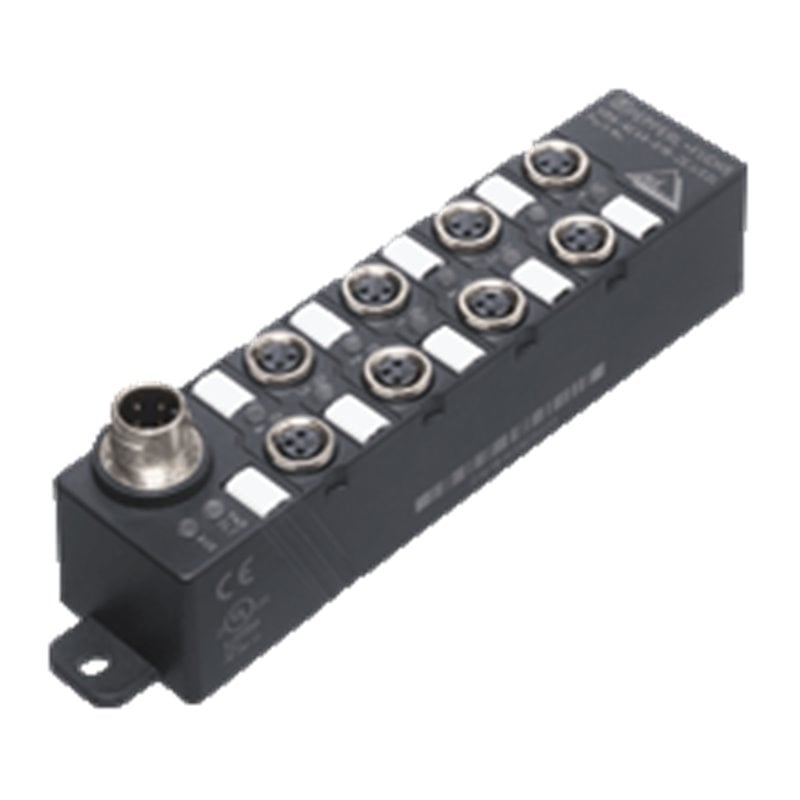
AS-Interface sensor/actuator module VAA-4E4A-G16-ZEJ/E2L VAA-4E4A-G16-ZEJ/E2L Compact design Connections via round connector AS-Interface connection via M12 metal threaded insert with SPEEDCON Function display for bus, ext. auxiliary voltage, inputs and outputs Degree of protection IP67 / IP68 / IP69K Inputs for 2- and 3-wire sensors Supply for inputs from AS-Interface Power supply of outputs from the external auxiliary voltage Communication monitoring Detection of overload on sensor supply Detection of output overload with LED per channel AS-Interface sensor/actuator module VAA-4E4A-G16-ZEJ/E2L VAA-4E4A-G16-ZEJ/E2L Compact design Connections via round connector AS-Interface connection via M12 metal threaded insert with SPEEDCON Function display for bus, ext. auxiliary voltage, inputs and outputs Degree of protection IP67 / IP68 / IP69K Inputs for 2- and 3-wire sensors Supply for inputs from AS-Interface Power supply of outputs from the external auxiliary voltage Communication monitoring Detection of overload on sensor supply Detection of output overload with LED per channel
MPNs 188849, PEP188849, VAA-4E4A-G16-ZEJ/E2L
税则号 85371091
Weight
0.15 kg
产品图片仅供参考,具体以实物为准
原产国、HS 编码和产品描述由制造商提供,如有变更,恕不另行通知。因此,PLC-City 不对任何差异承担责任。
由 PLC-CITY® 销售并从意大利发货
安全支付


 等等
等等
我们接受多种支付方式:银行转账(SEPA,ACH)、借记卡/信用卡(万事达、VISA、美国运通、大来、Discover、JCB、银联)、PayPal、ApplePay、GooglePay、Stripe链接支付、Cartes Bancaires、支付宝、Bancontact、blik、eps、giropay、iDeal、Przelewy24、微信支付。
有关我们付款方式的更多信息
12个月 保修
本产品享有12个月的保修期,保修范围涵盖制造缺陷或故障。保修不包括因不当使用或意外损坏造成的损害。
进一步了解我们的保固
产品信息
描述
Datasheet excerpt: Technical data of
VAA-4E4A-G16-ZEJ/E2L
Product Description
G16 compact module 4 inputs (PNP) and 4 electronic outputs
General specifications
Node typeStandard node
AS-Interface specificationV3.0
Required gateway specification≥ V2.1
UL File NumberE223772
Functional safety related parameters
MTTFd190 a
Mission Time (TM)20 a
Diagnostic Coverage (DC)0 %
Indicators/operating means
LED PWR/FAULTStatus display; multi-colour LEDGreen: normal operationRed: communication faultFlashing yellow/red: address 0Flashing green/red: sensor supply or output overload
LED AUXext. auxiliary voltage UAUX; dual LED green/redgreen: voltage OKred: reverse voltage
LED INswitching state (input); 4 LED yellow
LED OUTSwitching status (output); 4 yellow/red LEDs Yellow: output activeRed: output overload
Electrical specifications
Auxiliary voltage (output)20 ... 30 V DC PELV
Rated operating voltage26.5 ... 31.6 V from AS-Interface
Rated operating current≤ 40 mA (without sensors) / max. 240 mA
Protection classIII
Surge protectionUAUX, Uin: Over voltage category III, safe isolated power supplies (PELV)
Input
Number/Type4 inputs for 2- or 3-wire sensors (PNP), DC
Supplyfrom AS-Interface
Voltage21 ... 31 V
Current loading capacity≤ 200 mA (TB ≤ 40 °C),≤ 150 mA (TB ≤ 70 °C), overload-proof and short-circuit protected
Input current≤ 9 mA (limited internally)
Switching pointaccording to DIN EN 61131-2 (Type 2)
0 (unattenuated)≤ 3 mA
1 (attenuated)≥ 5 mA
Signal delay< 1 ms (input/AS-Interface)
Output
Number/Type4 electronic outputs, PNP, overload and short-circuit proof
Supplyfrom external auxiliary voltage UAUX
Voltage≥ (UAUX - 0.5 V)
Current1 A per output
Usage categoryDC-13
Directive conformity
Electromagnetic compatibility
Directive 2014/30/EUEN 62026-2:2013 EN 61000-6-2:2005, EN 61000-6-4:2007
Standard conformity
Degree of protectionEN 60529:2000
Fieldbus standardEN 62026-2:2013
InputEN 61131-2
Emitted interferenceEN 61000-6-4:2007
AS-InterfaceEN 62026-2:2013
Noise immunityEN 61000-6-2:2005 EN 62026-2:2013
Programming instructions
ProfileS-7.0
IO code7
ID code0
ID1 codeF
ID2 codeE
Data bits (function via AS-Interface)InputOutput
D0 IN1 OUT1
D1 IN2 OUT2
D2 IN3 OUT3
D3 IN4 OUT4
Parameter bits (programmable via AS-i)function
P0Communication monitoringP0 = 0 monitoring = off, the outputs maintain the status if communication failsP0 = 1 monitoring = on, i.e. if communication fails, the outputs are deenergised (default settings)
P1Input filterP1 = 0 input filter on, pulse suppression ≤ 2 msP1 = 1 input filter off (default settings)
P2Synchronous modeP2 = 0 synchronous mode onP2 = 1 synchronous mode off (default settings)
P3not used
Ambient conditions
Ambient temperature-25 ... 70 °C (-13 ... 158 °F)
Storage temperature-25 ... 85 °C (-13 ... 185 °F)
Relative humidity85 % , noncondensing
Climatic conditionsFor indoor use only
Altitude≤ 2000 m above MSL
Shock and impact resistance30 g, 11 ms in 6 spatial directions 3 shocks10 g, 16 ms in 6 spatial directions 1000 shocks
Vibration resistance0.75 mm 10 ... 57 Hz , 5 g 57 ... 150 Hz, 20 cycles
Pollution degree3
Mechanical specifications
Degree of protectionIP67 / IP68 / IP69k
ConnectionAS-Interface and auxiliary voltage: M12 x 1 round connectorsensors/actuators: M8 x 1 round connector
Material
HousingPBT
Mass150 g
Tightening torque, cable gland0.4 Nm (M12 connector),0.2 Nm (M8 connector)
Mountingscrew mounting
Classifications
SystemClasscode
ECLASS 11.027242604
ECLASS 10.0.127242604
ECLASS 9.027242604
ECLASS 8.027242604
ECLASS 5.127242604
ETIM 8.0EC001599
ETIM 7.0EC001599
ETIM 6.0EC001599
ETIM 5.0EC001599
UNSPSC 12.139121535