

 EN
USD
EN
USD
-
MenuBack
-
Brands
-
- Technologies for :
-
Industry
-
-
- Automation
- Motors & Drives
- Safety
-
Sensors
- Accessories/spare parts for industrial sensors
- Detection
- Distance
- Scanners
- RFID
-
Process
- Liquid flow sensors
- Liquid flow meter
- Temperature transformers
- Pressure switches
- Pressure differential sensor
- Pressure transmitter
- Immersion temperature sensor, passive
- Liquid level sensor
- Radar level sensor
- Vibration sensor
- Ultrasonic level meter
- Capacitive level sensor
- Temperature and climate measuring instruments
- Temperature probes
- Current value transformers
- Isolation amplifiers
- Machine vision system (MVS)
- Rotary encoders
- Connect
- Signal Cables
- Weighing
- Valves & Controls
-
Industrial Plugs & Sockets
- Panel-mounted CEE socket outlet (IEC 60309)
- CEE coupling (IEC 60309)
- CEE plug (IEC 60309)
- CEE socket outlet combination (IEC 60309)
- CEE appliance inlet (IEC 60309)
- CEE socket outlet (IEC 60309)
- CEE socket outlet, disconnectable, with fuse (IEC 60309)
- Explosion proof CEE socket outlet (IEC 60309)
- Accessories/spare parts for CEE plugs and sockets (IEC 60309)
- Explosion proof CEE plug/coupler (IEC 60309)
- Explosion proof switches
- Accessories/spare parts for test and measurement instruments
- Energy Monitoring
-
-
-
Building
-
-
- Green Power
- HVAC - Climatisation
- Lighting
- Monitor & Networking
- e-Mobility
-
Automation - Bus Systems
-
Control Elements
- Analogue input for bus system
- Basic module for bus system
- Binary input for bus system
- Central device for bus system
- Controller for home automation systems
- Display for bus system
- I/O device for bus system
- Logic component for bus system
- Signalling and operation panel for bus system
- Light control unit for bus system
- Room temperature controller for bus system
- Sensors
- Actuators
- Bus Communications
- Programming
- Others
-
Control Elements
-
Domestic switching devices
- Socket outlet combinations
- Cover frames for domestic switching device
- Mounting for labelling material
- Plug adapters
- Socket outlets
- Plugs with protective contact
- Insert/cover for communication technology
- Installation switches
- Movement sensors/presence detectors complete
- Push buttons
- Control elements/cover plates for domestic switching devices
- USB power supplies
- Sensor elements for movement sensor
- Power distribution units (PDU)
- Energy consumption indication
- Emergency call system devices
- Clinic installation system devices
- Pluggable building installation systems
-
-
-
Electrification
-
-
- Cables
-
Installation
-
Accessories for cables and tubes
- Bends for installation tubes
- Cable entry sleeve
- Cable gland
- Cable plug sealing clamp
- Cable tie mounts
- Cable ties
- Coupler for installation tubes
- Enlargement/reducing ring
- Fixing clamps
- Locknut for cable screw gland
- Plug for cable screw gland
- Sealing rings
- Tee/cross for installation tubes
- Threaded bush
- Accessories for wall mounted back boxes
-
Isolation and connection
- Accessories/spare parts for installation and connection material
- Adhesive tape
- Branch-splice joint (set)
- Breakout boots / Heat-shrink moulded shapes
- Cable end sleeve
- Cable insulation hose
- Connection for screened wires
- Connector for luminaire
- Crimp cable lug for aluminium conductors
- Crimp cable lug for copper conductors
- Push in terminal
- Shrink tubing
- Junction boxes
- Metal installation tubes
-
Protective hose systems
- Braided hose
- Cable bundle hose
- Corrugated plastic hose
- Coupler for corrugated plastic hoses
- Protective metallic hose
- Protective plastic hose
- Screw connection for corrugated plastic hose
- Screw connection for protective metallic hose
- Screw connection for protective plastic hose
- Sealing for hose screw connection
- Terminal sleeve for protective hose
- Saddle clamps (pipe/cable)
- Slotted cable trunking systems
- Terminal for luminaire
- Tube clamps
-
Accessories for cables and tubes
-
Low Voltage
- ASC Distribution Boards for Construction Sites
- Batteries and battery modules
-
Cabinets & Enclosures
- Bases & base elements
- Clima Control
- Door/operating panels
- Electronic enclosures
- Empty cabinets
-
Energy distribution systems
- Accessories/spare parts for busbar trunks
- Accessories/spare parts for busbars
- Busbar couplers
- Busbar supports
- Busbar trunk units
- Cover caps for rail terminal bar
- Covers for distribution boards
- Distributor assembly miniature circuit breakers (MCB)
- Distributor assembly terminal blocks
- Feed units for busbar trunk
- Main line branch terminals
- Meter cabinets equipped
- Mounting plates for distribution board
- Mounting rails
- Mounting systems for busbar trunk
- Panel for distribution board
- Phase barrier plates
- Small distribution board
- Tap off units for busbar trunk
- Explosion proof enclosures/housings
- Front panel (enclosure/cabinet)
- Keys for enclosures/cabinets
- Lock systems for enclosure/cabinet
- Mounting accessories for enclosures/cabinets
- Network cabinet
- Network/server enclosure
-
Circuit Breakers
- Auxiliary contact blocks
- Busbar adapters
- Device circuit breakers
- Earth leakage circuit breakers
- Fuse switch disconnectors
- Fuses
- Main lines circuit breakers
- Miniature circuit breakers (MCB)
- Off-load switches
-
Power Circuit Breakers
- Chassis parts power circuit breakers
- Door coupling handles
- Handles for power circuit breakers
- Modification set for power circuit breakers
- Motor operators for power circuit-breakers
- Phase separation plates for power circuit breakers
- Shunt release (for power circuit breakers)
- Switch spools for power circuit breakers
- Trip blocks for power circuit-breakers
- Under voltage coils
- Wiring set for power circuit breakers
- Residual current circuit breakers (RCCB)
- Surge protection devices for power supply systems
- Trip indicators
-
Command devices (Buttons, selectors, indicators)
- Accessories/spare parts for command devices
- Accessories/spare parts for emergency stop pull cord switches
- Acoustic indicators
- Adapters for command devices
- Buttons
- Control circuit devices combination in enclosure
- Control switches, Joysticks
- Emergency stop complete buttons
- Emergency stop pull cord switches
- Enclosures for control circuit devices
- Foot switches
- Indicator / pilot lights
- Indicator / pilot lights
- Legend plates for control circuit devices
- Potentiometers for command devices
- Protective caps for command devices
- Selectors
- Signal towers
- Text plates for command devices
- Two-hand control devices
- Contactors
- Data/Signal Line Surge Protection
- DIN-rail adapters
- Filters for low-voltage
- Low Voltage Accessories
-
Motor start & protection
- Accessories/spare parts for electronic motor controls and protection devices
- Electronic overload relays
- Extension modules for motor management devices
- Motor management devices
- Motor protection circuit-breakers
- Motor starters/motor starters combination
- Operator panels for motor management devices
- Soft starters
- Thermal overload relays
- Power Capacitors
- Power supplies
-
Relays
- (Fill) level monitoring relays
- Accessories/spare parts for switching relays
- Current monitoring relays
- Installation relays
- Insulation and earth fault monitoring relays
- Latching relay
- Optocoupler
- Phase monitoring relays
- Relay sockets
- Relays for thermistor protection (PTC)
- Residual current monitoring relays
- Solid state relays
- Speed-/standstill monitoring relays
- Switching relays
- Temperature monitoring relays
- Timer blocks
- Timer relays
- Voltage monitoring relays
- Surge protection modules
- Switch disconnectors (low voltage)
-
Terminal blocks
- (Knife) disconnect terminal blocks
- Accessories/spare parts for terminals
- Component plug terminal blocks
- Component terminal blocks
- Cross-connectors for terminal blocks
- End brackets for terminal blocks
- Endplates and partition plates for terminal blocks
- Feed-through terminal blocks
- Fuse terminal blocks
- Ground terminal blocks
- Labelling for terminal blocks
- Multi level installation terminal blocks
- Sensor/actuator terminal blocks
- Shield connection clamps
- Single- and multi-pole terminal strips
- Terminal block connectors
- Test plugs for terminal blocks
- Transformers & coils
- Marking
- Optical and acoustic signalling
- UPS
-
-
-
Tools
-
- Contact Us
- About Us
- Promo
-
PLC-City
Via Circumvallazione esterna 12
80025 Casandrino NA
Italy
-
MenuBack
-
Brands
-
- Technologies for :
-
Industry
-
-
- Automation
- Motors & Drives
- Safety
-
Sensors
- Accessories/spare parts for industrial sensors
- Detection
- Distance
- Scanners
- RFID
-
Process
- Liquid flow sensors
- Liquid flow meter
- Temperature transformers
- Pressure switches
- Pressure differential sensor
- Pressure transmitter
- Immersion temperature sensor, passive
- Liquid level sensor
- Radar level sensor
- Vibration sensor
- Ultrasonic level meter
- Capacitive level sensor
- Temperature and climate measuring instruments
- Temperature probes
- Current value transformers
- Isolation amplifiers
- Machine vision system (MVS)
- Rotary encoders
- Connect
- Signal Cables
- Weighing
- Valves & Controls
-
Industrial Plugs & Sockets
- Panel-mounted CEE socket outlet (IEC 60309)
- CEE coupling (IEC 60309)
- CEE plug (IEC 60309)
- CEE socket outlet combination (IEC 60309)
- CEE appliance inlet (IEC 60309)
- CEE socket outlet (IEC 60309)
- CEE socket outlet, disconnectable, with fuse (IEC 60309)
- Explosion proof CEE socket outlet (IEC 60309)
- Accessories/spare parts for CEE plugs and sockets (IEC 60309)
- Explosion proof CEE plug/coupler (IEC 60309)
- Explosion proof switches
- Accessories/spare parts for test and measurement instruments
- Energy Monitoring
-
-
-
Building
-
-
- Green Power
- HVAC - Climatisation
- Lighting
- Monitor & Networking
- e-Mobility
-
Automation - Bus Systems
-
Control Elements
- Analogue input for bus system
- Basic module for bus system
- Binary input for bus system
- Central device for bus system
- Controller for home automation systems
- Display for bus system
- I/O device for bus system
- Logic component for bus system
- Signalling and operation panel for bus system
- Light control unit for bus system
- Room temperature controller for bus system
- Sensors
- Actuators
- Bus Communications
- Programming
- Others
-
Control Elements
-
Domestic switching devices
- Socket outlet combinations
- Cover frames for domestic switching device
- Mounting for labelling material
- Plug adapters
- Socket outlets
- Plugs with protective contact
- Insert/cover for communication technology
- Installation switches
- Movement sensors/presence detectors complete
- Push buttons
- Control elements/cover plates for domestic switching devices
- USB power supplies
- Sensor elements for movement sensor
- Power distribution units (PDU)
- Energy consumption indication
- Emergency call system devices
- Clinic installation system devices
- Pluggable building installation systems
-
-
-
Electrification
-
-
- Cables
-
Installation
-
Accessories for cables and tubes
- Bends for installation tubes
- Cable entry sleeve
- Cable gland
- Cable plug sealing clamp
- Cable tie mounts
- Cable ties
- Coupler for installation tubes
- Enlargement/reducing ring
- Fixing clamps
- Locknut for cable screw gland
- Plug for cable screw gland
- Sealing rings
- Tee/cross for installation tubes
- Threaded bush
- Accessories for wall mounted back boxes
-
Isolation and connection
- Accessories/spare parts for installation and connection material
- Adhesive tape
- Branch-splice joint (set)
- Breakout boots / Heat-shrink moulded shapes
- Cable end sleeve
- Cable insulation hose
- Connection for screened wires
- Connector for luminaire
- Crimp cable lug for aluminium conductors
- Crimp cable lug for copper conductors
- Push in terminal
- Shrink tubing
- Junction boxes
- Metal installation tubes
-
Protective hose systems
- Braided hose
- Cable bundle hose
- Corrugated plastic hose
- Coupler for corrugated plastic hoses
- Protective metallic hose
- Protective plastic hose
- Screw connection for corrugated plastic hose
- Screw connection for protective metallic hose
- Screw connection for protective plastic hose
- Sealing for hose screw connection
- Terminal sleeve for protective hose
- Saddle clamps (pipe/cable)
- Slotted cable trunking systems
- Terminal for luminaire
- Tube clamps
-
Accessories for cables and tubes
-
Low Voltage
- ASC Distribution Boards for Construction Sites
- Batteries and battery modules
-
Cabinets & Enclosures
- Bases & base elements
- Clima Control
- Door/operating panels
- Electronic enclosures
- Empty cabinets
-
Energy distribution systems
- Accessories/spare parts for busbar trunks
- Accessories/spare parts for busbars
- Busbar couplers
- Busbar supports
- Busbar trunk units
- Cover caps for rail terminal bar
- Covers for distribution boards
- Distributor assembly miniature circuit breakers (MCB)
- Distributor assembly terminal blocks
- Feed units for busbar trunk
- Main line branch terminals
- Meter cabinets equipped
- Mounting plates for distribution board
- Mounting rails
- Mounting systems for busbar trunk
- Panel for distribution board
- Phase barrier plates
- Small distribution board
- Tap off units for busbar trunk
- Explosion proof enclosures/housings
- Front panel (enclosure/cabinet)
- Keys for enclosures/cabinets
- Lock systems for enclosure/cabinet
- Mounting accessories for enclosures/cabinets
- Network cabinet
- Network/server enclosure
-
Circuit Breakers
- Auxiliary contact blocks
- Busbar adapters
- Device circuit breakers
- Earth leakage circuit breakers
- Fuse switch disconnectors
- Fuses
- Main lines circuit breakers
- Miniature circuit breakers (MCB)
- Off-load switches
-
Power Circuit Breakers
- Chassis parts power circuit breakers
- Door coupling handles
- Handles for power circuit breakers
- Modification set for power circuit breakers
- Motor operators for power circuit-breakers
- Phase separation plates for power circuit breakers
- Shunt release (for power circuit breakers)
- Switch spools for power circuit breakers
- Trip blocks for power circuit-breakers
- Under voltage coils
- Wiring set for power circuit breakers
- Residual current circuit breakers (RCCB)
- Surge protection devices for power supply systems
- Trip indicators
-
Command devices (Buttons, selectors, indicators)
- Accessories/spare parts for command devices
- Accessories/spare parts for emergency stop pull cord switches
- Acoustic indicators
- Adapters for command devices
- Buttons
- Control circuit devices combination in enclosure
- Control switches, Joysticks
- Emergency stop complete buttons
- Emergency stop pull cord switches
- Enclosures for control circuit devices
- Foot switches
- Indicator / pilot lights
- Indicator / pilot lights
- Legend plates for control circuit devices
- Potentiometers for command devices
- Protective caps for command devices
- Selectors
- Signal towers
- Text plates for command devices
- Two-hand control devices
- Contactors
- Data/Signal Line Surge Protection
- DIN-rail adapters
- Filters for low-voltage
- Low Voltage Accessories
-
Motor start & protection
- Accessories/spare parts for electronic motor controls and protection devices
- Electronic overload relays
- Extension modules for motor management devices
- Motor management devices
- Motor protection circuit-breakers
- Motor starters/motor starters combination
- Operator panels for motor management devices
- Soft starters
- Thermal overload relays
- Power Capacitors
- Power supplies
-
Relays
- (Fill) level monitoring relays
- Accessories/spare parts for switching relays
- Current monitoring relays
- Installation relays
- Insulation and earth fault monitoring relays
- Latching relay
- Optocoupler
- Phase monitoring relays
- Relay sockets
- Relays for thermistor protection (PTC)
- Residual current monitoring relays
- Solid state relays
- Speed-/standstill monitoring relays
- Switching relays
- Temperature monitoring relays
- Timer blocks
- Timer relays
- Voltage monitoring relays
- Surge protection modules
- Switch disconnectors (low voltage)
-
Terminal blocks
- (Knife) disconnect terminal blocks
- Accessories/spare parts for terminals
- Component plug terminal blocks
- Component terminal blocks
- Cross-connectors for terminal blocks
- End brackets for terminal blocks
- Endplates and partition plates for terminal blocks
- Feed-through terminal blocks
- Fuse terminal blocks
- Ground terminal blocks
- Labelling for terminal blocks
- Multi level installation terminal blocks
- Sensor/actuator terminal blocks
- Shield connection clamps
- Single- and multi-pole terminal strips
- Terminal block connectors
- Test plugs for terminal blocks
- Transformers & coils
- Marking
- Optical and acoustic signalling
- UPS
-
-
-
Tools
-
- Contact Us
- About Us
- Promo
VBA-4E4A-KE5-ZEJQ/R PEPPERL+FUCHS - Part number: 263814
PEPPERL+FUCHS
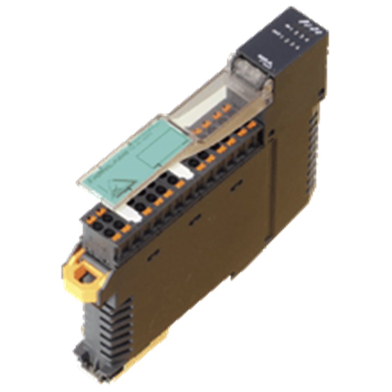
AS-Interface sensor/actuator module VBA-4E4A-KE5-ZEJQ/R VBA-4E4A-KE5-ZEJQ/R Housing with push-in connection technology and mechanically coded terminal blocks Housing width 19 mm, installation in the switch cabinet on DIN mounting rail Selectable supply to the sensors: External or from the module Function display for bus, internal sensor supply, inputs, and outputs AS-Interface sensor/actuator module VBA-4E4A-KE5-ZEJQ/R VBA-4E4A-KE5-ZEJQ/R Housing with push-in connection technology and mechanically coded terminal blocks Housing width 19 mm, installation in the switch cabinet on DIN mounting rail Selectable supply to the sensors: External or from the module Function display for bus, internal sensor supply, inputs, and outputs
The product image is for illustrative purposes only.
The country of origin, HS code, and description are provided by the manufacturer and may be subject to change without prior notice. For this reason, PLC-City cannot be held responsible for any discrepancies.


 & many more
We accept many payment methods: Bank Transfer (SEPA, ACH), Debit/Credit Cards (Mastercard, VISA, American Express, Diners Club, Discover, JCB, UnionPay), PayPal, ApplePay, GooglePay, link by Stripe, Cartes Bancaires, Alipay, Bancontact, blik, eps, giropay iDeal, Przelewy24, WeChatPay.
More information about our payment methods
This product is covered by a 12 Months warranty, valid for manufacturing defects or malfunctions. The warranty does not cover damage caused by improper use or accidental damage.
Learn more about our warranty
Returns are subject to prior authorization and eligible for store credit only. Backordered items are excluded.

 & many more
We accept many payment methods: Bank Transfer (SEPA, ACH), Debit/Credit Cards (Mastercard, VISA, American Express, Diners Club, Discover, JCB, UnionPay), PayPal, ApplePay, GooglePay, link by Stripe, Cartes Bancaires, Alipay, Bancontact, blik, eps, giropay iDeal, Przelewy24, WeChatPay.
More information about our payment methods
This product is covered by a 12 Months warranty, valid for manufacturing defects or malfunctions. The warranty does not cover damage caused by improper use or accidental damage.
Learn more about our warranty
Returns are subject to prior authorization and eligible for store credit only. Backordered items are excluded.